The information contained in this document is the property of Automatic Systems and is confidential. The recipient shall refrain from using it for any purpose other than the use of the products or the
execution of the project to which it refers, and from communicating it to third parties without Automatic Systems’ prior written agreement. Document subject to change without notice.
BL3x-MT-EN-08
page
49/59
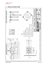
a
b
1
2
3
4
5
X
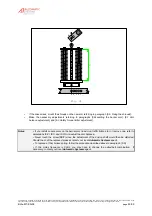
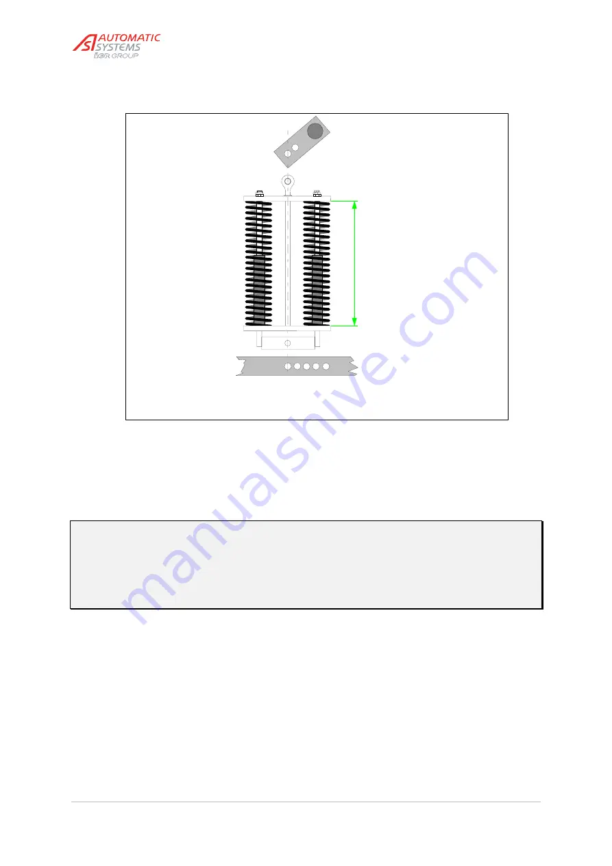
Fig. 31
--
If the case arises, mount the shrouds on the new arm referring to
paragraph [5.6. Fixing the shrouds]
.
--
Make the necessary adjustments referring to
paragraphs [5.8Levelling the barrier arm]
,
[6.1 Arm
balance adjustment]
, and
[6.3 Safety torque limiter adjustment]
.
Notes:
-- If you install an accessory on the barrier arm (road sign, traffic lights, etc.) or remove one, refer to
paragraphs [5.8], [6.1] and [6.3] to re-adjust the arm balance.
-- Never touch the screw (30:7) since the adjustment of the driving shaft would then be distorted.
Should the shaft be replaced, please contact your local Automatic Systems agent.
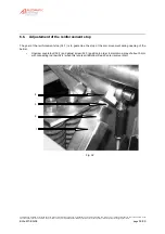
-- To replace a (the) broken spring, follow the procedure described above in paragraph [6.5].
-- If the mains frequency is 60Hz, you may have to change the pulley/belt combination. If
necessary, contact your local Automatic Systems agent.


