The information contained in this document is the property of Automatic Systems and is confidential. The recipient shall refrain from using it for any purpose other than the use of the products or the
execution of the project to which it refers, and from communicating it to third parties without Automatic Systems’ prior written agreement. Document subject to change without notice.
BL3x-MT-EN-08
page
30/59
5.2.
Handling and installing the unit
•
The barrier has been packaged in a wood crate for transport. Carry the material to the installation site with
the help of a trolley, place the crate upright and dismantle.
•
Unlock and remove the side door (
3:10
). Keys are attached on the arm-fixing jaw (
1:3
) or on the arm
bracket (
1:4
) or (
1:5
) by means of adhesive tape.
•
Unlock the two latches (
3:16
) from inside and remove the hood (
3:11
).
•
Check the state of the equipment. Though it has been carefully packed, damage may have occurred during
transport: in this case, do not forget to advise your local
Automatic Systems
agent or your insurance
company. If need be, proceed with the necessary repairs.
•
Strip the insulation of the cables along approx. 50cm.
•
Locate the hole of the emergency crank (
1:10
).
•
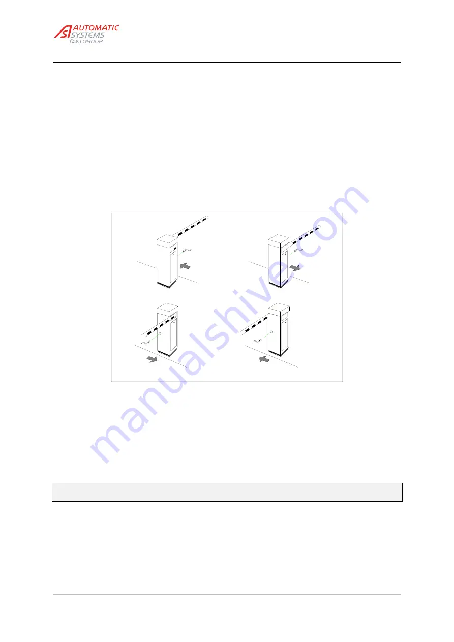
without damaging the anchoring bolts, place the housing (
1:7
) on its concrete base so that the crank hole is
at the same side as the roadway.
Fig. 9c
Solution 1 (standard)
Solution 2
Solution 3
Solution 4
•
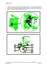
Insert the fixing bracket (
1:8
) inside the unit onto the two right-hand anchoring bolts (
9:1
) of the basement
kit.
•
Insert the fixing bracket (
1:9
) with the heater holder inside the unit on the two left-hand anchoring bolts.
•
Secure the barrier to the basement kit by locking the fixing brackets (
1:8
) and (
1:9
) with the flat washers
(
9:5
), the lock washers (
9:6
) and the nuts (
9:7
).
•
Fix the stainless steel heater (
3:13
) into the sheath provided on the left-hand fixing bracket (
1:9
).
•
If required, add shims between the sealing frame and the housing in order to ensure the barrier is perfectly
level.
Note:
Since final adjustment of the alignment with the roadway may be necessary after the arm is
installed, do not tighten the nuts (9:7) firmly now.


