The information contained in this document is the property of Automatic Systems and is confidential. The recipient shall refrain from using it for any purpose other than the use of the products or the
execution of the project to which it refers, and from communicating it to third parties without Automatic Systems’ prior written agreement. Document subject to change without notice.
BL3x-MT-EN-08
page
31/59
5.3.
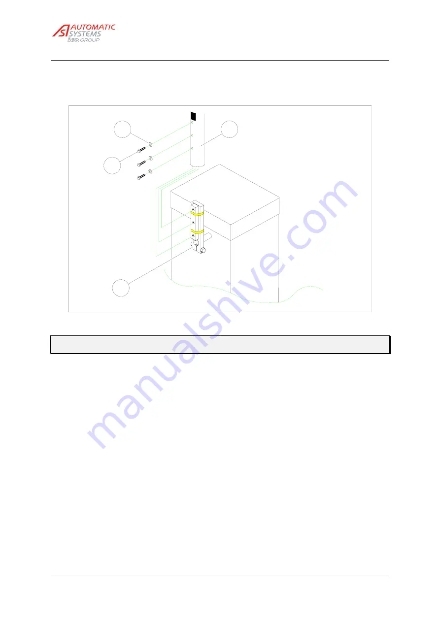
Installing the lateral arm (BL32)
Fig. 10
10:3
10:4
10:1
10:2
Attention
:
Fixing the arm requires two people!
(+ refer to "safety warnings" chapter!)
•
Remove the three screws (
10:1
) and flat washers (
10:2
) from the arm-fixing jaw (
10:3
).
•
Position the first segment (
10:4
) of the arm tube onto the arm-fixing jaw, and fix the flat washers (
10:2
) and
the screws (
10:1
) as illustrated above.
•
Check the alignment of the first segment with the arm-fixing jaw, and tighten the screws (
10:1
) firmly. The
first segment is now installed.
•
Lower the arm tube with the crank (
1:10
), helping the movement by hand if necessary, up to the horizontal
position. Continue turning the crank to make sure that the mechanism is locked.
•
After loosening the screws (
13:10
), insert the second segment (
13:9
) into the first and --if the case arises--
the third (
13:11
) into the second, then align the red reflecting stripes.
•
Tighten the screws (
13:10
) firmly again to secure the second and third arm segments.
•
Check the alignment of the complete barrier with the roadway and adjust if necessary.
•
If no tip support is to be installed, tighten the nuts (
9:7
) firmly to lock the barrier on the sealing frame.
•
If the case arises, install the shrouds now referred in
paragraph [4.6. Fixing the shrouds].


