

Electronic Pushbutton Locks
EL740S
© 2017 IDN, Inc. All rights reserved.
0817
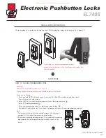
MAIN OPERATING INSTRUCTIONS
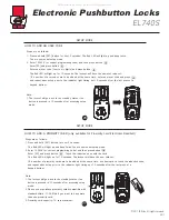
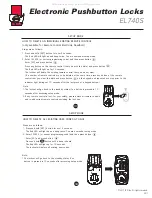
(only available for Proximity Card Electronic Deadbolt)
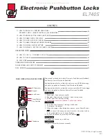
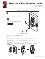
1. Inductive zone is around the keypad.
2. The proximity card we offer is the latest Radio Frequency
Identification (RFID) technology, compatible with standard
Mifare -13.56 MHz.
3. Unlock the door by touching the inductive zone with the
proximity card.
(Radio Frequency, RF)
(only available for Remote Control Electronic Deadbolt)
1. There is one unlock button and one lock button on the remote control.
2. Effective range of the controller is designed to be within 15 meters
(50 feet). However, the range could be affected by ambient temperature
and humidity.
3. The LED light of the remote control will be turned on when holding
the Lock Button for over 3 seconds.
1
2
3
4
5
6
7
8
9
0
C
Inductive
Zone
04
LED Indicator
Lock Button
Unlock Button
Inductive Zone & RFID Card:
Remote Control:
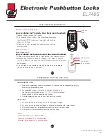
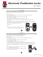
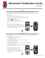
PROGRAMMING CODE AND USER CODE
PROGRAMMING CODE
05
1. Only one programming code will be allowed. The lockset can be programmed only by
entering the programming code.
2. A programming code is restricted to 6-digits in length only.
The pre-set programming code is
1-2-3-4-5-6
(factory setting).
Please change it before operating the lockset.
3. The programming code can be used to unlock the lockset.
USER CODE
1. A user code can be from four (4) to six (6) digits in length.
2. A user code can be changed (added or deleted) by accessing the setup mode.
3. The lockset cannot be programmed by entering any of the user codes.
4. The lockset will be unlocked by entering one user code.
Note:
User code capacity: 10 sets maximum.
Proximity card capacity: 10 sets maximum.
Remote control capacity: 10 sets maximum.
All manuals and user guides at all-guides.com


