**
PATENT No. 6,196,599 & 5,730,478
US
R
C
L
CLASSIFIED
U
c 2017 ABH Mfg., Inc.
printed in USA
www.abhmfg.com
E-mail: [email protected]
Architectural Builders Hardware Mfg., Inc.
1222 Ardmore Ave., Itasca, IL 60143
630.875.9900; FAX 800.9FAXABH (932.9224)
O
R
ISSUED 06-08-17
6100EO-1-00.DWG
12
LATCH CAM
2
11
4
5
6
2
3
1
10
SQUARE
-OR-
ROUND
COVER
COVER
#8 x 3/4" FHWS
#10 STAR WASHER
LATCH
12-24 x 1-7/8" FHMS
8-32 x 3/8" FHMS
10-32 x 1/4" PAN HD. M.S.
PUSH OR PULL HANDLE ASSY
12-24 x 1/2" SEX BOLT
ADAPTER PLATE
.
8
2
12
11
1
2
10
9
.
4
4
2
2
5
6
7
1
3
4
4
1
ITEM
1
QTY
1
PART DESCRIPTION
#12 x 1/2" PHSMS STAKING SCREWS
13
1
6100EO
PAGE 1 OF 3
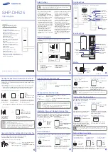
6100EO SERIES EXIT ONLY PUSH/PULL HANDLE
INSTALLATION RETROFIT FOR 161 PREP
(NO ADDITIONAL THRU BOLTS REQUIRED)
DETAIL "A"
NOTE:
BEFORE MOUNTING PUSH AND PULL
HANDLES, CAM PIN MUST BE ROTATED
TOWARDS SIDE INDICATED BY ARROW
STAMPED ON THE BASE.
ALL PREP MOUNTING HOLES
TO BE STRAIGHT & PARALLEL
TO ONE ANOTHER, THIS WILL
HELP PREVENT ANY BINDING
OF MECHANICAL PARTS.
NOTES
1. TRIM CAN BE MOUNTED UP, DOWN, HORIZONTALLY OR VERTICALLY.
2. USES STANDARD 161 DOOR PREP.
3. VISION LITE MUST BE AT LEAST 6" FROM CENTERLINE OF TRIM.
HORIZONTAL
BACKSET
WITH 7"
HANDLE
BACKSET
HANDLE
HORIZONTAL
WITH 5" OR 7"
DOWN
HANDLES
UP
HANDLES
*
*
13
CAM SHAFT
STAKING SCREW HOLE
8
7
EXIT ONLY PLATE
1
INSTALLATION INSTRUCTIONS:
1. Door to be machined for standard 161 .
2. Install latch (item 12) using either #8 FHWS (item 11) or 8-32 FHMS (item 2) depending on door material type.
3. Before mounting adapter plate (item 6) & exit only plate (item 8), determine which side of the door will receive the push or pull handle
assembly (item 4) and the direction the handle will mount. Handle can be mounted up, down or horizontally.
4. Mount adapter plate (item 6) & exit only plate (item 8) to door with (2) 12-24 screws (item 5) thru door and latch to (2) 12-24 sex
bolts (item 7). tighten securely.
5. Before mounting handle assembly (item 4), cam pin must be rotated towards the correct side of the handle (see detail A).
6. Mount handle assembly (item 4) to adapter plate (item 6) with (4) 10-32 screws (item 3) with (4) star washers (item 10).
7. Test lock for proper operation. If latch bolt does not extend or retract freely because of any type of binding, loosen mounting screws
to adjust alignment of trim handle assembly (item 4) and re-tighten screws one at a time while checking latch bolt movement.
8. To prevent the handle assembly from possible twisting, which in turn can cause binding, determine which staking screw hole will be
used for the handle assembly (the staking screw installs on the staking screw hole location opposite the direction the handle is
mounted). Install staking screw using #12 PHSMS (item 13).
9. Place cover (item 1) over handle assembly (item 4) and secure with (2) 8-32 screws (item 2) on each side.