22
Concord Super Series 4 -
Installation & Servicing
The
Ideal Concord Super
boiler must be commissioned and
tested by a qualified gas/heating engineer. A knowledge of
electrical wiring is necessary.
Upon request, Ideal Boilers, will provide a quote for
commissioning or re-commissioning after servicing.
Make sure that the electrical supply to the boiler is OFF at
the main isolator switch. Remove the orange module covers.
Check that the black mains voltage plug on the left-hand side
of each module is pulled out.
FILLING THE BOILER WITH WATER
Fill the system by admitting water at the lowest point. This will
ensure air is forced from the tubes of the heat exchangers.
WATER CIRCULATION
Switch on the pump motor and check that water is circulating
and the pump is vented.
Check the operation of the water flow switch. It should switch
off the electrical supply to the modules if the water flow rate
fails below two-thirds of design water flow rate (in Tables 1 &
2).
HEADER GAS SOUNDNESS & PURGING THE GAS LINE
Turn the top module gas service tap ON. Connect a
manometer to the tapping point at the top of the gas header
(see Frame 14 & PTP1 - Frame 29).
Slacken the nut on the union, connecting the top module to
the gas header, and purge the gas header by turning the
mains inlet gas tap on until gas is smelt then re-tighten the
union connection.
Turn off the top module gas service tap and ensure all other
module gas service taps are in the off position. Take note of
the manometer reading and turn off the mains gas inlet tap.
A subsequent fall in pressure indicates a leak between the
mains inlet gas tap and individual module gas service taps
which MUST be made good.
The mains inlet gas tap can then be turned on again.
CONTROL LINE GAS SOUNDNESS (Frames 14, 17 & 29)
Carry out the following test on each module in turn:
1.
Turn on the module gas service tap
2.
Turn off the mains inlet gas tap, and observe the
manometer pressure as above. This pressure should
NOT fall by more than 2.5 mbar (1 in.w.g.) in one
minute. If this rate of fall is exceeded, leakage past the
combination gas control seat or leakage from joints in this
section of gas line MUST be investigated.
3.
Turn off the module gas service tap and continue with the
next module.
Pre-firing check (refer Frames 15, 16, 17 & 18).
Ensure that:
a.
The electrical supply to the boiler is OFF.
b.
The orange covers are removed.
c.
The black mains plugs on the left side of each module
are removed.
Note:
EXTREME CARE SHOULD BE TAKEN WHEN THE
MODULE IS RUN WITHOUT A COVER.
Each module should be checked as follows:
1.
Switch the module on/off switch to OFF. (Frame 16
2.
Turn the module gas service tap to OFF.
3.
Check that the low voltage 10-way plug is fitted to printed
circuit board No. 28.
4.
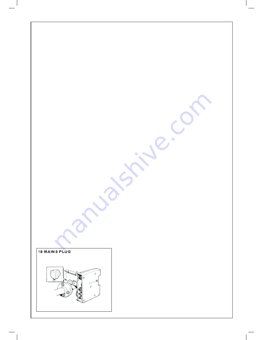
Fit the black mains voltage plug into the connection point
on the left-hand side of the module (refer Frame 18).
5.
Switch ON the electrical supply to the boiler at the main
isolator switch.
6.
Switch the module on/off switch to ON.
The following sequence of events will occur:
a.
The module mains ‘ON’ light will be illuminated.
b.
For multi-module boilers: The fans will start and run for
approx 30 seconds (part of the 3 volume air change
safety feature). The fan will stop for from 1 to 50 secs.
depending on its position in the switching order. It will
then restart & run for approx. 15 sec. If the lockout
warning light illuminates at this stage press the lockout
reset button.
For single module boilers: the fan will start and run for
approximately 15 seconds.
c.
The ignition spark commences, continues for 4 seconds
then ceases. (The spark can be seen through the sight
glass in the module front).
d.
At the end of the 4 second ignition period, the combustion
lockout light will be illuminated. The mains ON light will
remain illuminated and the fan will continue to run.
e.
Turn the module on/off switch to OFF. The lights will be
extinguished and the fan will stop.
Turn OFF the electrical supply to the boiler.
DIFFERENTIAL PRESSURE
Connect n inclined gauge to measure the pressure difference
across the multi-hole plate. The pressure tapping is connected
to the lower pressure test point of the gas-air ratio control and
the suction tapping to the upper test point (Frame 20).
If when the fan is operating on air alone the differential
air pressure is less than 1.1 mbar (0.44 in.w.g.) the
commissioning procedure must not continue.
Check the soundness of the connections and the fan
performance.
Note.
It is not possible to check the soundness of the suction
line connections using leak detection fluid.
COMMISSIONING AND TESTING
Summary of Contents for Concord Super Series 4 100 V
Page 2: ......
Page 39: ...37 Concord Super Series 4 Installation Servicing ...


