28
Concord Super Series 4 -
Installation & Servicing
FERNOX DS. 10 does NOT produce fumes or toxic gases,
but it is recommended to work under good conditions of
ventilation.
Contact with zinc, aluminium, magnesium, cement, asbestos
and bathtub enamel MUST be MINIMISED or, at best,
COMPLETELY AVOIDED.
KEEP ALL CHEMICALS AWAY FROM CHILDREN
Materials and spares required in addition to those listed
under servicing:
1.
A solution of Fernox DS.10 or Sentinel dry side cleanser.
2.
Container, minimum dimensions 350mm x 350mm x
350mm.
3.
Gas distribution screen (aluminium wrapper) and screws.
4.
40mm nominal bore gaskets (module to header).
5.
Triangular gaskets between module flow and return
headers and top cover plate.
6.
Cover plate gasket (top).
7.
Cover plate gasket (bottom).
Preparing the boiler
1.
Unscrew the two retaining screws from the front of the
orange cover and remove the cover.
2.
Withdraw the multi-pin plug from the left-hand side of the
module and switch off the module on/off switch.
3.
Unscrew the two M4 screws at the right-hand edge of the
control panel and open the front control panel door (refer
to Frame 19).
4.
Unplug the low voltage 10-way plug from the top right-
hand corner (viewed from inside) of the circuit
board and
withdraw it through the rear control panel.
Note.
The captive catch on the side of the 10-way plug
must be un-latched.
5.
Unscrew the three cable clips securing the low voltage
harness at the left-hand side of the control panel support
bracket and pull the harness clear.
6.
Close the control panel front door and secure with the
two M4 screws.
7.
Isolate the boiler from the flow and return water pipes.
8.
Drain the boiler.
9.
Uncouple the flanges connecting the modules to the flow
and return headers.
10.
Release the union nuts connecting the gas inlet manifold
to the modules.
11.
Remove the fan, burner with ignition electrode and
the flame sensing probe, as described in the Servicing
Instructions.
12.
Remove the module gas line as follows.
i.
Remove the four M4 x 10mm lg. pozi-screws
securing the injector pipe to the cast iron return
pipe.
ii.
Remove the nut securing the gas line bracket to its
fixing stud.
13.
Withdraw the adjustable control thermostat and safety
temperature limiter sensors from their pockets.
14.
Unscrew the two M5 x 10mm lg. pozi-screws securing the
control panel support bracket to the angle bracket and
remove the control panel assembly.
15.
Unscrew the four M10 nuts securing the module to the
casing and withdraw the module.
16.
Unscrew the screws holding the gas distribution screen
over the finned tubes and remove the screen.
The module heat exchanger is now ready for cleaning.
Preparing the solution
For normal cleaning, dissolve Fernox DS. 10 or Sentinel dry
side cleanser in water to make a solution in the proportions of
7 kg. per 70 litres of water.
This should provide a solution strength to adequately clean a
lightly scaled heat exchanger in approximately five minutes,
depending upon the severity of the scaling. In order to reduce
the cleaning time, a more concentrated solution may be made
of proportions up to but NOT exceeding 2 kg. per 10 litres of
water.
Pour the solution into a suitable container - the MINIMUM
dimensions of which should be 350mm x 350mm x 350mm.
A container of this size will require approximately 28 litres (6
gallons) of prepared solution to set up the initial bath.
When more than one module is to be cleaned, additional
solution should be prepared for topping up the container.
Note.
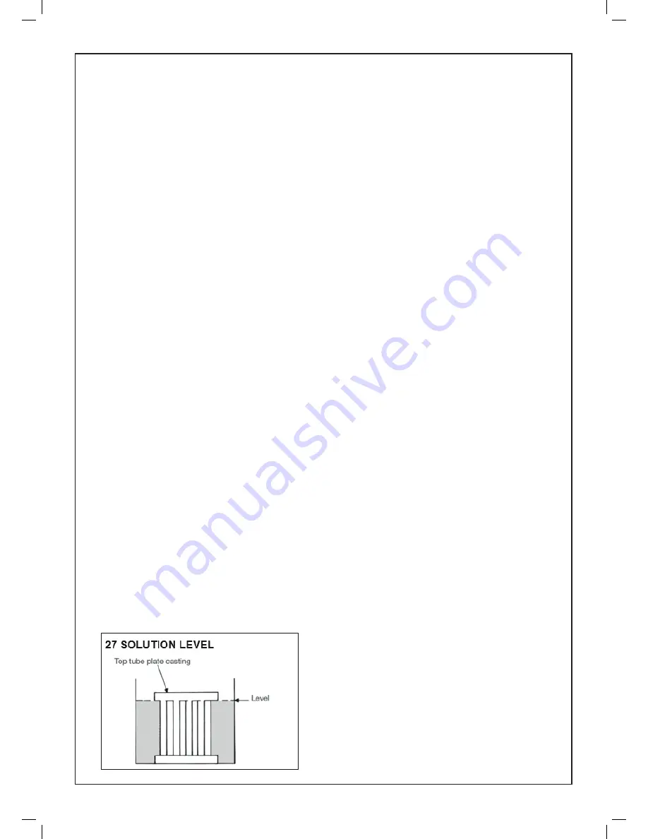
Refer Frame 27
There should be sufficient solution in the container to ensure,
with the module immersed, that the solution level just reaches
the underside of the top tube plate casting.
Cleaning
1.
Immerse the module in the solution.
The period of immersion will depend upon the severity of
the scaling.
Lightly scaled tubes can be successfully cleaned in
approximately five minutes.
Note.
For best results, agitate the module periodically in
the solution.
2.
Remove the module from the container and
THOROUGHLY rinse - a length of hose, fitted with a
piece of flattened copper tube to form a nozzle, will be
found adequate for this purpose.
3.
For severely scaled heat exchangers, it may be
necessary to remove any remaining stubborn deposits by
brushing and then re-immersing into the solution for a few
minutes.
In extreme cases it may be necessary to repeat this
process.
After the final immersion, the heat exchanger should be
given a THOROUGH rinse.
4.
Repeat the cleaning operation for each module, topping
up the solution each time to the underside of the top tube
plate casting.
SERVICING AND FAULT FINDING
Summary of Contents for Concord Super Series 4 100 V
Page 2: ......
Page 39: ...37 Concord Super Series 4 Installation Servicing ...


