24
Concord Super Series 4 -
Installation & Servicing
CO2 (as read) 1.9 2.6 3.2 3.9 4.5 5.1 5.8 6.4 7.1 7.7 8.4 9.0 9.6 10.3 10.9 11.6
Maximum allowable 15 20 25 30 35 40 45 50 55 60 65 70 75 80 85 90
CO p.p.m. (as read)
7.
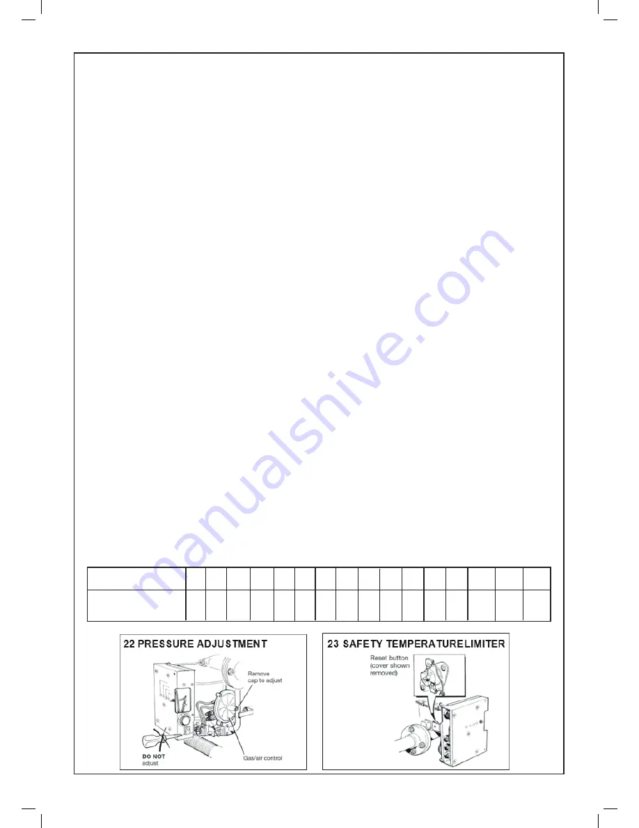
If adjustment is necessary remove the screw cap of the
gas/air control unit which projects horizontally at the far
right-hand side of the module (refer Frame 22).
DO NOT ATTEMPT TO ADJUST THE FACTORY PRE-
SET GAS RATE LIMITER WHICH FACES YOU ON THE
FRONT OF THE GAS VALVE.
Using a screwdriver, turn the adjustment screw within the
projecting tube under the cap until the gas valve outlet
pressure is 6.8 mbar (2.7 in.w.g.).
Switch the module OFF and then ON again to check that
the pressure is correct, again allowing several minutes
of firing for the pressure to stabilize. If the setting is
consistently repeated, refit the screw cap of the gas/air
control unit.
8.
Switch OFF, disconnect the manometers and screw down
the sealing screws within the gas valve test points. Close
the front panel and retain with the M5 pozi-drive screw.
SAFETY CHECKS TO BE CARRIED OUT ON ALL
MODULES
1. Ensuring lockout
With the module running, turn off the gas service tap.
The burner will stop firing, the burner ON light will be
extinguished and the fan will run on. A single attempt to
relight will be made as follows: After approx. 15 seconds
during which only the mains light is illuminated, the
ignition sequence will start, the spark will operate for 4
seconds after which the lockout and mains on light will be
illuminated. The fan will run on. If this sequence of events
does not occur, replace printed circuit board No. 28 to
which the lights are attached.
2. Combustion
Fire each module, on its own, blanking off the fan air
inlets of ALL the NON-FIRING modules. using the sheets
of self adhesive paper supplied in the module hardware
pack. Measure CO and CO
2
for each module. A sampling
point is provided in the top of the boiler casing, adjacent
to the flue outlet socket (Frame 14).
For DRAEGAR tests note the following:
a.
The sampling line, however short, should ALWAYS be
purged.
b.
CO
2
tubes are marked in per cent divisions and ONE
pump only is required. CO tubes are also marked in
divisions indicating parts per million (p.p.m).
c.
The ratio % CO / CO
2
should not exceed 0.001. For
convenient reference, the table below (Table 5) shows
maximum CO levels in p.p.m. (read direct from tube)
related to various CO
2
levels.
Low CO2 levels are included to cover dilutions due to
casing and flue volume on the larger boilers.
Remove the fan inlet blanking material from all modules
and fire all modules together. Measure the gas pressure
at the gas header test point and ensure that it is not less
than 15 mbar (6 in.w.g.).
Check also that the draught stabiliser is controlling
draught between neutral and 0.2 mbar (0.08 in.w.g.).
With all modules firing, measure CO and CO
2
levels
again and refer to Table 5 for maximum allowable CO
content.
IMPORTANT
After the combination tests have been conducted it is essen-
tial that in order to comply with the European requirements
to provide a three times the casing volume to pre-purge the
boiler should always be left to operate with at least half the
modules switched on and their fans in working order.
3. Detector current
The main burner flame detector current may be checked
by breaking the in-line connector lead and inserting a
micro-ammeter. The flame current should be 6-8 µA.
4. Safety temperature limiter
If the water flow rate through the boiler is adequate the
safety temperature limiter should not operate when the
load on the boiler is GRADUALLY reduced from maxi-
mum to minimum.
The safety temperature limiter is mounted on the steel
panel at the left-hand side of the module. Reset by push-
ing in the ‘reset’ button (Refer to Frame 23).
ONCE COMMISSIONING HAS BEEN COMPLETED,
ALL MODULE COVERS SHOULD BE REPLACED.
Ensure that all module on/off switches are left in the ON
position.
Table 5 MAXIMUM ALLOWABLE CO CONTENT
COMMISSIONING AND TESTING
Summary of Contents for Concord Super Series 4 100 V
Page 2: ......
Page 39: ...37 Concord Super Series 4 Installation Servicing ...


