background image

  F/N 522803 Jul12 

© 2012 ICS, Blount Inc.

814PRO SERVICE MANUAL

7

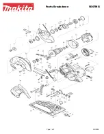
4. SPARE PARTS DIAGRAM

KEY P/N DESCRIPTION

1

74514 HSH Cap Screw 10-24 x 1 1/4

2

74515 Rear Gear Housing Assembly

3

74516 Dowl Pin

4

74517 Bushing (4)

5

74518 O-Ring

6

74519 Idler Shaft

7

74520 Idler Gear

8

74021 Wallwalker Pivot Pin

9

74597 1/8 NPT Plug

10

74596 Wiper Seal

11

74522 Drive Gear (with Keyway)

12

74523 On-Off Valve

13

74524 Hydraulic Valve Seal

14

74525 Spring Washer

15

74526 Spring

16

74527 Retaining Ring 1/2 External

17

74528 Plug Button

18

74529 Roll Pin

19

74530 Roll Pin

20

74531 Valve Handle Assy (Includes: 31, 66)

21

74532 O-Ring

22

74533 Pigtail Hose Assembly

23

74534 1/2” Flush Face Coupler (M)

24

74535 1/2” Flush Face Coupler (F)

25

74536 Water Hose Assembly

26

74537 Trigger

27

74538 Spring 

28

74539 Safety Catch (Trigger Lock-Out)

29

74540 Rear Stud

30

74542 Roll Pin

31

74543 O-Ring

32

74544 O-Ring

33

74545 Self Locking Retaining Ring

34

74546 O-Ring

35

74547 Water Valve Sleeve

36

74548 O-Ring

37

74549 Pin

38

74550 Steel Ball

39

74551 Spring

40

74552 O-Ring

41

74553 Seal Cap

42

71386 Splined Sprocket Adaptor

43

71384 External Shaft Retaining Ring

44

74497 Seal Spacer

45

71385 Rim Sprocket

KEY P/N DESCRIPTION

46

71388 Tabbed Washer

47

71940 Side Cover Replacement Kit

48 74558 Flange Nut (M10)
49

74559 Sprocket Side Cover Seal

50

71383 814PRO Motor Shaft Replacement

51

74561 Needle Roller

52

74562 HSH Cap Screw 5/15-18 x 3/4

53 74563 Shaft Seal
54 74564 Seal Back Up Washer
55

74591 Guard Flap Assembly (Not shown)

56 74566 Guard Flap Mount
57

74567 Spacer

58 74568 Bar Mount Cover Plate
59 74569 Front Stud
60

74570 HSH Cap Screw 1/4-20 x 5/8

61

74571 Machine Screw

62

74572 Stat-O-Seal

63

74573 Bar Adjustment Nut

64

74019 Lanyard Assembly

65 74582 WallWalker Spring
66 74583 WallWalker Arm (w/ Spring)
67

74574 Handle Bar Retainer

68

74575 Handle Bar

69 74584 Guard Mounting Bolt
70

74585 Guard Mounting Washer

71

74586 Front Handguard

72

74576 Washer

73

74577 HH Cap Screw 5/16-18 x 5/8, Zinc

74

74588 Handlebar Grip

75

74579 Nut 1/4-20 HHD LT SST

76

74580 Spiral Pin

77

74581 Spiral Pin

78

74493 Quad-Ring

79

74565 Retaining Ring

80 74554 Shaft Bearing Race
81

74498 O-Ring

82 74495 Seal Washer
83 74494 V-Ring
84 74496 Seal Ring
85 74555 Retaining Ring

71152 Tensioning Scrench, Hydraulic Saws (not shown)

71944 Water Valve Seal Kit (Incl: 31,32,34,36) (not shown)

71945

Motor Shaft Seal Kit (Incl: 5,43,53,54,78,81,83) shown on 
p.8

74061 Chain Tensioning Assembly (Incl: 61,62,63,75) (not shown)
75260 814 Rim Sprocket Upgrade Kit (not shown)

Summary of Contents for SpeedHook 814PRO

Page 1: ...F N 522803 Jul12 2012 ICS Blount Inc 814PRO SERVICE MANUAL...

Page 2: ......

Page 3: ...RO SERVICE MANUAL 1 SHOP MANUAL USE 2 1 TOOLS 3 2 SAW SPECIFICATIONS 4 3 SERIAL NUMBER LOCATION 5 4 SPARE PARTS DIAGRAM 6 5 MOTOR ASSEMBLY 8 6 WATER VALVE ASSEMBLY 24 7 TROUBLESHOOTING DIAGRAM 30 SECT...

Page 4: ...et to separate parts attached solidly to each other Mark mating parts as a reassembly reference Keep component parts together as a group Assemble screws and nuts into appropriate subgroups When reasse...

Page 5: ...l12 2012 ICS Blount Inc TITLE 814PRO SERVICE MANUAL 3 1 TOOLS 1 Tools available for the 814PRO Hydraulic Saw KEY P N DESCRIPTION SERVICE 71572 TOOL KIT 1 71152 SCRENCH 17 19 mm 2 73462 MAIN BEARING DR...

Page 6: ...equirements Max 8 gpm l min 2 500 psi 172 bar Hydraulic Fluid Requirements Type Mobil DTE 13M or Equivalent Water Pressure Requirements Minimum 20 psi 1 4 bar Recommended 20 psi 1 4 bar Maximum 160 ps...

Page 7: ...F N 522803 Jul12 2012 ICS Blount Inc TITLE 814PRO SERVICE MANUAL 5 3 SERIAL LOCATION 3 814PRO Hydraulic Saw serial number series...

Page 8: ...2012 ICS Blount Inc F N 522803 Jul12 814PRO SERVICE MANUAL 6 4 SPARE PARTS DIAGRAM 12 32 45 46 47 84 59 79 78 58 62 73...

Page 9: ...1385 Rim Sprocket KEY P N DESCRIPTION 46 71388 Tabbed Washer 47 71940 Side Cover Replacement Kit 48 74558 Flange Nut M10 49 74559 Sprocket Side Cover Seal 50 71383 814PRO Motor Shaft Replacement 51 74...

Page 10: ...tor Shaft Seal Kit so that all seals exposed during disassembly can be replaced P N 71945 A Remove the 2 nuts 51 and then lift off the side cover 50 B Lift off the bar 61 and chain 73 If it is necessa...

Page 11: ...rrent models and slide off items 43 45 and 46 Use retaining ring 43 for replacement P N 71384 e clip D Remove the retaining ring 43 and then spacer 44 E Remove the retaining ring 85 and then items 81...

Page 12: ...pry the gear housing away from the valve handle Lift the gear housing straight up DO NOT tilt the housing or pry on the at surface inside of the surrounding groove For prying only use the groove provi...

Page 13: ...surrounding surface J While protecting the motor surface of the valve handle from damage tap lightly on the small diameter end gear side of the motor shaft 50 to remove it K To remove the bearing from...

Page 14: ...g ring 79 at the bottom of the bearing bore Remove the seal backup washer 54 Remove the quad ring 78 and o ring 53 using the appropriate o ring service tools Discard the quad ring and o ring M The bus...

Page 15: ...The chamber bores and bottoms around the shaft bushings should be polished and not rough or grooved If the bushing bores are yellow bronze replace them and investigate the cause of wear The at surface...

Page 16: ...ive gear keyway and gear tooth root Replace the gear if cracks are present E VALVE HANDLE MOTOR SURFACE The surface near the gears should show two interconnecting polished circles without a step The b...

Page 17: ...ticles may have been imbedded in the bushings grinding into the hardened shaft If abnormal shaft wear as above occurs more than normal polishing replace both the shaft and associated bushings Also che...

Page 18: ...to the valve handle assembly Replace the retaining ring 79 B To replace the bearing 80 onto the motor shaft 50 support the bearing inner race and press the motor shaft through the bearing inner race C...

Page 19: ...aft seal Using a socket with a diameter equal to the bearing O D press the bearing and motor shaft into place Press only on the outer race E Install the needle roller 51 in the keyway of the motor sha...

Page 20: ...g 5 H Note the screw hole pattern on the rear gear housing and the valve handle They will only assemble one way With all parts aligned carefully slide the gear housing assembly over the gears until it...

Page 21: ...capscrews 1 and then recheck rotation Snug screws and check shaft rotation again For final torque turn 1 4 rotation past snug and recheck rotation K Install the o ring 81 Push in until it contacts th...

Page 22: ...seal ring 84 then with both in hand apply a small amount of 242 Loctite TM to the bore of the seal ring N Make sure it is applied around the entire bore of the seal ring then slide both parts onto the...

Page 23: ...F N 522803 Jul12 2012 ICS Blount Inc 814PRO SERVICE MANUAL 21 P Install items 42 45 and Retainer clip 43 5 MOTOR ASSEMBLY...

Page 24: ...nt nut 63 off by turning the adjustment screw 61 counter clockwise B Install the chain guide plate 58 over the studs 29 59 C Install the chain onto the bar Place the bar with chain over the studs maki...

Page 25: ...up on the bar and chain turn the adjustment screw 61 clockwise to take the slack out of the chain E Install the side cover 47 and the 2 nuts 48 Hand tighten the 2 nuts and then back them off 1 4 turn...

Page 26: ...ssembly can be replaced P N 71944 6 2 ON OFF VALVE SERVICING TRIGGER AND SAFETY CATCH REMOVAL INSTALLATION A Remove the plug button 19 from the top of the handle by prying under the edge and then pull...

Page 27: ...VAL INSTALLATION A Unscrew the seal cap 41 and remove it the o ring 40 the spring 39 and the steel ball 38 B Remove the plug button 17 wiper seal 10 and the retaining ring 16 from handle The wiper sea...

Page 28: ...valve spool bore from the plug button end of the handle D Push the dowel against the water valve sleeve 32 37 to push the water sleeve out Remove o ring 31 from the spool bore of the handle If only t...

Page 29: ...light surface scratches will be noticeable Grooves roughness or a reduced diameter indicate uid contamination If abnormal wear is present more than normal polishing replace both the spool and the hand...

Page 30: ...valve sleeve 35 into the valve handle F Install the steel ball 38 spring 39 and seal cap 41 Make sure a new o ring 40 is installed onto the seal cap G If the spring washer 14 and spring 15 were remove...

Page 31: ...8 making sure the spring 27 is positioned properly Make sure the pin 30 is in place Secure the safety catch with the roll pin 19 I Install the trigger 26 and secure with the roll pins 18 J Replace the...

Page 32: ...cal failure Have tool serviced by authorized dealer Tool runs backwards Pressure and return lines incorrectly connected Correct hose connections Motor shaft rotates counterclockwise as viewed from the...

Page 33: ......

Page 34: ...ICS Blount Inc 4909 SE International Way Portland OR 97222 Tel 800 321 1240 Fax 503 653 4393 icsbestway com 814PRO SERVICE MANUAL...

Reviews: