background image

82

6

CONNECTION AND INSTALLATION

2001 NEW

2001 NEW

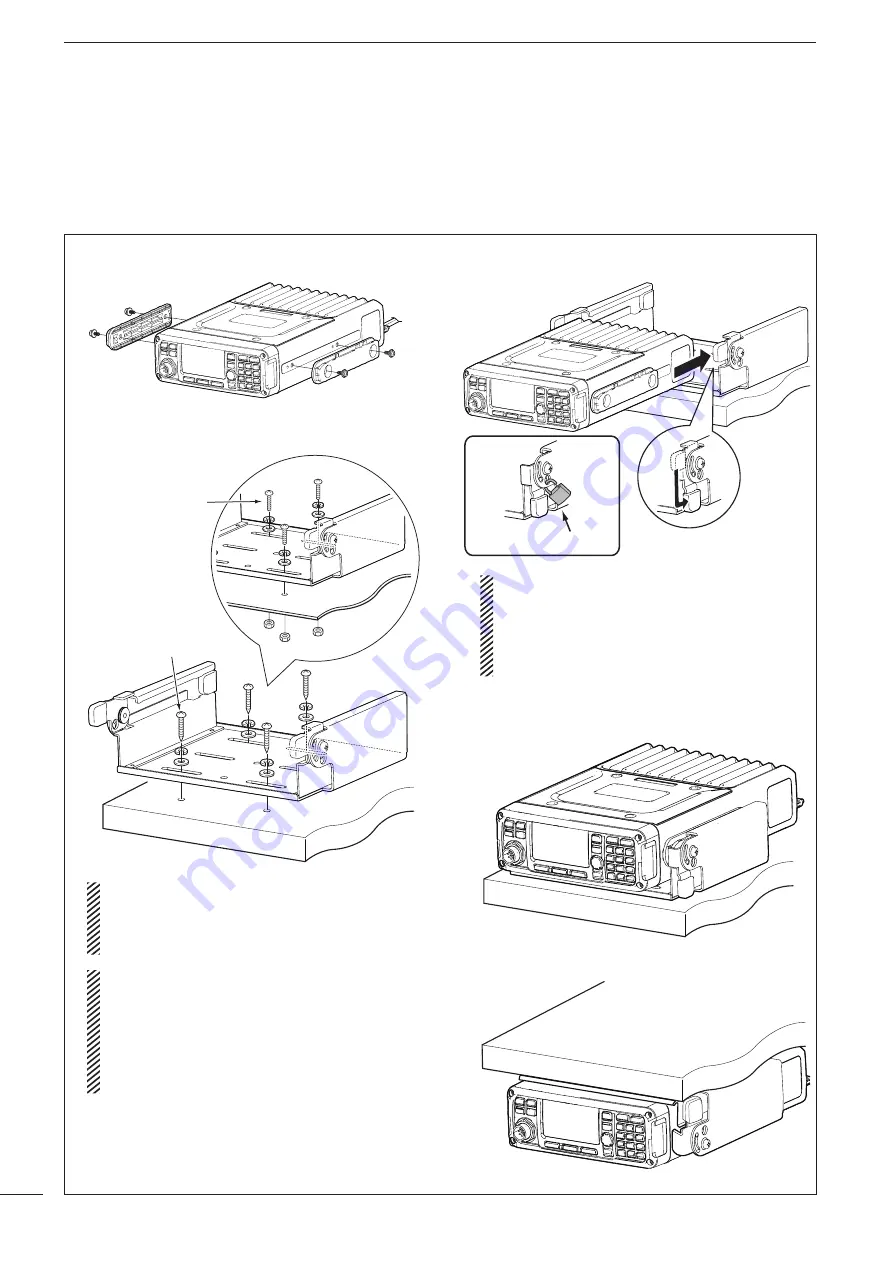
q

  Attach the mounting plates and tighten the 2 sup-

plied M5 

×

 8 mm screws on each side.

w

  Place the mounting bracket on the board, and then 

tighten the 4 supplied screws.

M5 × 16 mm

M5 × 12 mm


R

WARNING!


Mount the mounting bracket to 

a surface that can support more than 10 kg 
(22 lb). The unit must be mounted on only a flat 
hard surface.

 When using the M5 × 16 mm tapping screws:

  Mount the mounting bracket to a board that is 

more than 20 mm (0.8 inches) thick.

 When using the M5 × 12 mm screws:

  Mount the mounting bracket to a board to which 

you can firmly tighten the screws with the wash-
ers and nuts.

e

  Attach the Main unit to the mounting bracket, as 

shown below.

Not supplied by Icom


Attention to mount on the board:

  If the supplied rubber feet are attached to the 

Main unit (p. 73), remove them before attaching 
it to the mounting bracket. Otherwise the feet 
get stuck, and you cannot slide the Main unit 
into the bracket.

r

  The completed mounting should look like this.

• Surface mounting

• Overhead mounting

MB-126 (Optional mounting bracket)

An optional MB-126 mounting bracket is used to 
mount the transceiver or transceiver’s Main unit onto 
a flat surface.

Summary of Contents for IC-F8101

Page 1: ...HF TRANSCEIVER iF8101 INSTRUCTION MANUAL This device complies with Part 15 of the FCC Rules Operation is subject to the condition that this device does not cause harmful interference ...

Page 2: ...Incorporated Japan in Japan the United States the United Kingdom Germany France Spain Russia Australia New Zealand and or other countries All other products or brands are registered trademarks or trademarks of their respective holders Icom is not responsible for the destruction or damage to the Icom transceiver if the malfunction is because of Force majeure including but not limited to fires earth...

Page 3: ...ration 10 3 RECEIVE AND TRANSMIT 11 17 Basic voice transmit receive 11 Functions for transmit 12 Functions for receive 14 4 SELCALL ALE OPERATION 18 38 Selcall ALE 18 5 MENU SCREEN 39 71 Manager Menu 39 Main Menu 52 CPU Reset 71 6 CONNECTION AND INSTALLATION 72 85 Supplied accessories 72 Connections 74 Ground connection 76 Power source 77 Antenna 77 CFU F8100 Optional Cooling Fan 77 RMK 6 Optional...

Page 4: ...inimum distance of 200 centimeters away from the properly installed antenna This separation distance will ensure that there is sufficient distance from a properly installed externally mounted antenna to satisfy the RF ex posure requirements in the applicable RF expo sure compliance standards CAUTION To ensure that your exposure to RF electromagnetic energy is within the FCC and IC allowable limits...

Page 5: ...loin d une antenne correc tement fixée à l extérieur pour satisfaire aux exi gences en matière d exposition aux RF en vertu des normes de conformité applicables MISE EN GARDE Afin de vous assurer que votre expo sition à une énergie électromagnéti que de RF se situe dans les limites permises par la FCC et d IC pour une utilisation grand public veuillez en tout temps respecter les directives suivant...

Page 6: ...NOT use or place the transceiver in direct sunlight or in areas with temperatures below 30 C 22 F or above 60 C 140 F The basic operations transmission and reception of the transceiver are guaranteed within the specified operat ing temperature range However the LCD display may not be operate correctly or show an indication in the case of long hours of operation or after being placed in extremely c...

Page 7: ...r 2 seconds to turn OFF the power rCALL KEY Push to enter the Call menu Push again to go to the next screen in the Call menu Hold down for 1 second to enter the Network selec tion screen tUP DOWN KEYS r s Selects the operating channel the items in the Menu mode and so on yENTER KEY 4 Push to enter and exit the selected Menu in the Menu screen Hold down for 1 second to enter the setting mode uCLEAR...

Page 8: ...AF r OPTION MIC DET t PTT y GND u GND microphone ground i 8 V DC output Max 1 A 1LOCK KEY Hold down for 1 second to set the Key lock function to ALL NUMERIC KEY or OFF DKeypad Inputs numbers characters or letters 10 key Front panel HM 192 Selectable characters KEY INPUT INPUT KEY space Upper Lower case letters Numbers 1 Q Z q z 2 A B C a b c 3 D E F d e f 4 G H I g h i 5 J K L j k l 6 M N O m n o ...

Page 9: ...Antenna tuner p 11 Push to turn OFF the Antenna tuner DISPLAY KEY DISP Push to select the display information Frequencies Latitude and Longitude Direction and Elevation Antenna SWR and Power source voltage and Date and Time can be selected Latitude and Longitude and Direction and El evation require data from a GPS unit MUTE KEY MUTE Push to select the squelch type Call squelch S meter squelch leve...

Page 10: ... op tional cable is not connected t ACCESSORY CONNECTOR 15 PIN ACC Connects to an optional UX 248 gps unit Connects to a GPS unit or an external modem through the optional OPC 2308 gps extmod con nection cable When connecting a GPS unit the transceiver sets your position and time data in NMEA0183 version 3 xx format NOTE Attach the connector caps when the op tional unit or cable is not connected y...

Page 11: ...display Displays the channel name VFO display Displays the operating frequency oSUB READOUTS Memory Channel display Displays the selected information Frequencies Latitude and Longitude Direction and El evation Antenna SWR and Power source voltage and Date and Time can be displayed Latitude and Longitude and Direction and Elevation re quire data from a GPS unit When the frequencies are displayed th...

Page 12: ...ks when a Channel Test call is trans mitted or while waiting for its acknowledgement The icon blinks or appears when an RFDS Emer gency call is transmitted or linked ALE The icon blinks when an Individual or Individual Update LQA calls is transmitted or while waiting for an acknowledgement The icon stays ON when the Individ ual call is linked The icon blinks either when a NET or NET Up date LQA ca...

Page 13: ...o select the character group ABC upper case letters abc lower case letters or 123 numbers Push 8 to delete a character Push t or u to move the cursor NOTE If you want to change any settings you must be in the Administrator mode You can log into the Administrator mode with the Admin Login item in the Manager Menu screen p 40 Keypad Power ON q q Push 8 to enter the Main Menu screen w w Push r or s t...

Page 14: ...enu Setmode Config Mute icon The Mute icon S L or V appears when the squelch function Call SQL S meter SQL or Voice SQL is ON NOTE The Call squelch function cannot be se lected in the VFO mode Push or to adjust the audio level If the squelch is closed push MUTE M one or more times to open the squelch The display shows the volume level while adjusting Minimum audio level Maximum audio level Squelch...

Page 15: ...e changed in the Mode item of Setmode Main Menu Setmode q q Select the Display mode q Push 8 to enter the Main Menu screen w Push r or s to select Channel or VFO and then push 4 w Push Mode 3 one or more times to select the desired mode The selected mode icon appears at the top of the display NOTE On the Memory Channel display the selected operating mode can be used only temporarily When the chann...

Page 16: ...er the decimal point Push 8 to delete the number Push t or u to move the cursor r r Push 4 to save the frequency and exit Keypad Turning ON the Split frequency function q q Push 8 to enter the Main Menu screen w w Select the VFO Split item of Setmode q Push r or s to select the item and then push 4 to open the screen Setmode Config w Push r or s to select VFO Split and then hold down 4 for 1 secon...

Page 17: ...E 9 for 1 second to start the an tenna tuner If the antenna cannot be tuned after 20 seconds the tuning circuit is automatically bypassed After tuning is finished the transceiver automatically stops transmitting If necessary push 8 to manually stop transmitting Presetting An optional antenna tuner must be connected The antenna tune mode must be set to ON in the Tuner item of Setmode Default ON Mai...

Page 18: ...the default setting r r Push 4 to save the setting and return to the pre vious screen t t Push 8 one or more times to exit D D Setting Microphone gain The microphone gain must be properly adjusted so that your signal is not distorted when transmitted Default q q Push 8 to enter the Main Menu screen w w Select the Mic Gain item of Setmode q Push r or s to select the item and then push 4 to open the...

Page 19: ...screen If desired adjust the Speech Processor Level See the next topic for details t t Push 8 one or more times to exit y y Push MODE 3 one or more times to select the USB or LSB mode u u Hold down PTT on the microphone and speak at your normal voice level D D Speech Processor Level The Speech Processor level must be properly adjust ed so that your signal is not distorted when transmit ted Default...

Page 20: ...n dow D D Preamp and Attenuator The preamp amplifies received signals in the front end circuit to improve the S N ratio and sensitivity Turn ON this function to better receive weak signals The attenuator prevents strong undesired signals near the desired frequency or near your location such as from a broadcast station from causing distortion or spurious signals Default q q Push 8 to enter the Main...

Page 21: ...h 4 to save the setting and return to the pre vious screen If desired adjust the Noise Blanker Level or Noise Blanker Depth See the next topic for details t t Push 8 one or more times to exit D D Noise Blanker adjustment To deal with various types of noise the threshold level and attenuation level can be set by the Noise Blanker Level and Noise Blanker Depth items Default q q Push 8 to enter the M...

Page 22: ...to re turn to the default setting When AUTO is selected the AGC time constant varies depending on the operating mode r r Push 4 to save the setting and return to the pre vious screen t t Push 8 one or more times to exit D D AGC OFF function When receiving weak signals with adjacent strong signals or noise the AGC function may reduce the sensitivity In this situation the AGC function should be turn...

Page 23: ... to turn OFF the function D D Clear Talk Level The Clear Talk Level must be adjusted for maximum readability Setting the Clear Talk Level too high re sults in audio signal masking or distortion Default q q Push 8 to enter the Main Menu screen w w Select the Clear Talk Level item of Setmode q Push r or s to select the item and then push 4 to open the screen Setmode Config w Push r or s to select Cl...

Page 24: ...oltage signal strength output power VSWR and so on Stun call Only Open Selcall The Stun call disables the specified station from either transmitting and receiving RFDS emergency call Only Australian versions The RFDS Royal Flying Doctor Service emergency call uses a 2 Tone signal for an emergency call Emergency call Allows you to send an emergency signal along with your own position information Th...

Page 25: ...ed Push t or u to move the cursor Push 8 to delete the digit to the left of the cursor This Call ID is not saved in the Call ID list t t Push r or s to select the Profile then push y y Push r or s to select the channel Only the channels that belong to the Network selected in step w are displayed If desired push Tests to transmit the Channel Test call in this step u u Push to transmit the Selective...

Page 26: ...the keypad keys to enter the Phone Link ID and then push The previously entered Link ID is displayed Push t or u to move the cursor Push 8 to delete the digit to the left of the cursor This ID is not saved in the Phone Link ID list y y Push r or s to select the Profile then push u u Push r or s to select the channel Only the channels that belong to the Network selected in step w are displayed If d...

Page 27: ... then push The previously entered Call ID is displayed Push t or u to move the cursor Push 8 to delete the digit to the left of the cursor This Call ID is not saved in the Call ID list t t Select the desired Message or edit New message m Message selection Push r or s select the Message and then push m New Message input q Hold down 4 to enter the input mode w Push the keypad keys to enter the Messa...

Page 28: ...sor Push 8 to delete the digit to the left of the cursor This Call ID is not saved in the Call ID list t t Push r or s to select the Profile then push y y Push r or s to select the Channel Only the channels that belong to the Network selected in step w are displayed If desired push Tests to transmit the Channel Test call in this step u u Push to transmit the Send Position call While calling push o...

Page 29: ...saved in the Call ID list t t Push r or s to select the Profile then push y y Push r or s to select the Channel Only the channels that belong to the Network selected in step w are displayed If desired push Tests to transmit the Channel Test call in this step u u Push to transmit the Send Position call While calling push or PTT to cancel the call The call is saved in the Call Out memory You can als...

Page 30: ...hen push y y Push r or s to select the Channel Only the channels that belong to the Network selected in step w are displayed If desired push Tests to transmit the Channel Test call in this step u u Push to transmit the Send Position call While calling push or PTT to cancel the call The call is saved in the Call Out memory You can also make a Get Status call when the Ad dress screen is displayed In...

Page 31: ...Channel Only the channels that belong to the Network selected in step w are displayed If desired push Tests to transmit the Channel Test call in this step u u Push to transmit the Emergency call While calling push or PTT to cancel the call The call is saved in the Call Out memory You can also make an Emergency call when the Ad dress screen is displayed In this case you can skip several steps see p...

Page 32: ...gency Channel Test and Stun are selectable The Stun call is selectable in the Open Selcall r r Push the keypad keys to enter the Call ID and then push The previously entered Call ID is displayed Push t or u to move the cursor Push 8 to delete the digit to the left of the cursor This Call ID is not saved in the Call ID list t t Push r or s to select the Profile then push y y Push r or s to select t...

Page 33: ...ll r r Push the keypad keys to enter the Call ID and then push The previously entered Call ID is displayed Push t or u to move the cursor Push 8 to delete the digit to the left of the cursor This Call ID is not saved in the Call ID list t t Push the keypad keys to enter the specified sta tion s PIN Code and then push Push t or u to move the cursor Push 8 to delete the digit to the left of the curs...

Page 34: ...reen w w Push r or s to select the desired Network and then push The Networks that belong to the RFDS systems must be selected e e Push r or s to select the Channel Only the channels that belong to the Network selected in step w are displayed r r Push to transmit the RFDS emergency call While calling push or PTT to cancel the call The call is saved in the Call Out memory D D RFDS emergency call on...

Page 35: ...ired 4 Setting is required The contents is skipped Screen Entry Call system Network Call type Call ID Phone Link 4 Message 5 Self ID 3 Channel 6 Note Address Emergency Link 1 3 4 The skipped contents are used from the preset setting Call In Call Out 1 3 4 The skipped contents are used from the preset setting Phone Link 1 4 4 4 The Call type is always set to Phone The skipped contents are used from...

Page 36: ...ush Only the IDs that belong to the Network selected in step w are displayed y y Push r or s to select the Channel Only the channels that belong to the Network selected in step w are displayed If Auto is selected the transceiver sequentially trans mits on channels that belong to the Network in the LQA order u u Push to transmit the Individual call While calling push or PTT to cancel the call After...

Page 37: ...the IDs that belong to the Network selected in step w are displayed y y Push r or s to select the Channel Only the channels that belong to the Network selected in step w are displayed If Auto is selected the transceiver sequentially trans mits on channels that belong to the Network in the LQA order u u Push to transmit the NET Call While calling push or PTT to cancel the call After calling the tra...

Page 38: ...ter the Message Push A a to toggle between the Upper case letter and Number input mode Push 8 to delete the character symbol or num ber to the left of the cursor Push t or u to move the cursor e Push 4 to save the Message This Message is not saved in the Message list u u Push r or s to select the Channel Only the channels that belong to the Network selected in step w are displayed If Auto is selec...

Page 39: ...and Number input mode Push 8 to delete the character symbol or num ber to the left of the cursor Push t or u to move the cursor e Push 4 to save the Message This Message is not saved in the Message list u u Push r or s to select the Channel Only the channels that belong to the Network selected in step w are displayed If Auto is selected the transceiver sequentially trans mits on channels that belo...

Page 40: ...e Call Type to Sound ing Individual NET Call Individual AMD NET AMD Sounding Individual Update LQA NET Update LQA Unlink Individual AMD and Unlink NET AMD are select able r r Push r or s to select the Self ID then push Only the IDs that belong to the Network selected in step w are displayed t t Push r or s to select the Channel Only the channels that belong to the Network selected in step w are di...

Page 41: ... and then push Only the IDs that belong to the Network selected in step w are displayed t t Push r or s to select the Self ID then push Only the IDs that belong to the Network selected in step w are displayed y y Push r or s to select the Channel Only the channels that belong to the Network selected in step w are displayed If Auto is selected the transceiver sequentially trans mits on channels tha...

Page 42: ... to the Network selected in step w are displayed t t Push r or s to select the Self ID then push Only the IDs that belong to the Network selected in step w are displayed y y Push r or s to select the Channel Only the channels that belong to the Network selected in step w are displayed If Auto is selected the transceiver sequentially trans mits on channels that belong to the Network u u Push to tra...

Page 43: ... m Message selection Push r or s select the Message and then push m New Message input q Hold down 4 to enter the input mode w Push the keypad keys to enter the Message Push A a to toggle between the Upper case letter and Number input mode Push 8 to delete the character symbol or num ber to the left of the cursor Push t or u to move the cursor e Push 4 to save the Message This Message is not saved ...

Page 44: ... w Push the keypad keys to enter the Message Push A a to toggle between the Upper case letter and Number input mode Push 8 to delete the character symbol or num ber to the left of the cursor Push t or u to move the cursor e Push 4 to save the Message This Message is not saved in the Message list u u Push r or s to select the Channel Only the channels that belong to the Network selected in step w a...

Page 45: ...lf checks the transceiver s condition Auto Sequentially tests the Logic Receiver and Transmitter items Logic Tests the Logic item Receiver Tests the Receiver item Transmitter Tests the Transmitter item Create Entry Makes a new entry for ALE Channel Net work or Selcall ALE Makes new ALE items Call IDs Net IDs or Self IDs Call ID NET ID Self ID Channel Makes new memory channels Network Makes and reg...

Page 46: ...min Login may appear and then the password is requested e e Push the keypad keys to enter the Administrator password and then push 4 Repeatedly push A a to select the character group ABC upper case letters abc lower case letters or 123 numbers Push 8 to delete a character Push t or u to move the cursor Keypad D Return to the User mode q q Push MNGR to enter the Manager Menu screen Admin Logout is ...

Page 47: ... Locked and editing is restricted in the User mode The setting is effective after the transceiver returns to the User mode D D Setting the Access Rights View You can confirm the restriction of the memory chan nel Selcall address or any other settings Display example Appears when the Hidden setting is ON Appears when the Lock setting is ON Appears when the Factory Lock setting is ON This setting ca...

Page 48: ...ogic Receiver and Transmitter are select able If any problems are found Test failed appears If no problems are found Test passed appears D D Information You can display a variety of information by using the Information item q q Push MNGR to enter the Manager Menu screen Admin Logout is automatically selected w w Push r or s to select Information and then push 4 e e Push r or s to select the item a...

Page 49: ...pad keys to enter the desired ID and then push 4 Up to 15 characters can be entered Usable characters are A to Z 0 to 9 and Push A a to toggle between the Alphabet Upper case letter input mode and Number input mode Push 8 to delete the character symbol or number to the left of the cursor Push t or u to move the cursor r r If the entered ID belongs to a specified NET ID push r or s to select the NE...

Page 50: ...o enter the input mode w w Push the keypad keys to enter the Channel name and then push 4 Up to 20 characters can be entered See page 2 for the usable characters details Push A a to toggle between the Upper Lower case letter input modes and the Number input mode Push 8 to delete the character symbol or number to the left of the cursor Push t or u to move the cursor e e Push the keypad keys to ente...

Page 51: ...lect 4 appears to the left of the selected scan type If desired up to three scan types can be selected r r Hold down 4 for 1 second to go to the next screen t t Push r or s to select the Call system and then push 4 y y Push r or s to select the Call detect time and then push 4 u u Push r or s to select the Preamble and then push 4 Selectable times are 1 to 60 seconds and Auto i i Push r or s to se...

Page 52: ... mode Push 8 to delete the character symbol or number to the left of the cursor Push t or u to move the cursor r r Push r or s to select the Call type Then push the keypad keys to enter the ID or num ber and push 4 Push 8 to delete the character symbol or number to the left of the cursor Push t or u to move the cursor Call type is other than Phone Up to 6 digits can be entered Call type is Phone U...

Page 53: ...ween the Upper Lower case letter input modes and the Number input mode Push 8 to delete the character symbol or number to the left of the cursor Push t or u to move the cursor r r Push the keypad keys to enter the ID and then push 4 Up to 6 digits can be entered Push 8 to delete the character symbol or number to the left of the cursor Push t or u to move the cursor t t Push r or s to select a netw...

Page 54: ... r or s to select Profile and then push 4 to enter the input mode e e Push the keypad keys to enter the Profile name and then push 4 Up to 20 characters can be entered See page 2 for the usable characters details Push A a to toggle between the Upper Lower case letter input modes and the Number input mode Push 8 to delete the character symbol or number to the left of the cursor Push t or u to move ...

Page 55: ...ush the keypad keys to enter the Channel name and then push 4 Up to 20 characters can be entered See page 2 for the usable characters details Push A a to toggle between the Upper Lower case letter input modes and the Number input mode Push 8 to delete the character symbol or number to the left of the cursor Push t or u to move the cursor e e Push the keypad keys to enter the receive frequen cy and...

Page 56: ...reen r r Push s to select OK and then push 4 If desired select Cancel and then push 4 ALE Self ID A new Self ID can be created NOTE The present Self ID is cleared q q Push r or s to select ALE Self ID and then hold down 4 for 1 second to enter the input mode w w Push the keypad keys to enter the desired ID and then push 4 Usable characters are A to Z 0 to 9 and Push A a to toggle between the Alpha...

Page 57: ...s to select Selcall Profile and then hold down 4 for 1 second to enter the input mode w w Push the keypad keys to enter the desired ID and then push 4 Up to 6 numbers can be entered Usable characters are A to Z 0 to 9 and Push 8 to delete the number to the left of the cursor Push t or u to move the cursor e e Push s to select OK and then push 4 If desired select Cancel and then push 4 ...

Page 58: ...ction mode Slot Displays the Slot Slot selection mode Message Message Displays the preset Message list Message editing mode NET ID NET ID Displays the preset NET ID list NET ID editing mode Self ID Self ID Displays the preset Self ID list ID Displays the ID ID editing mode NET ID Displays the NET ID NET ID selection mode Network Displays the Network Network selection mode Slot Displays the Slot Sl...

Page 59: ... Name editing mode ID Displays the ID ID editing mode Network Displays the Network Network selection mode Channel Displays the Channel Channel selection mode Profile Profile Displays the preset Profile list Name Displays the ID Name editing mode ID Displays the ID Call type selection and ID or number editing mode Network Displays the Network Network selection mode D D Network Displays or edits the...

Page 60: ...cceptable level of ALE word cor rection data when it is decrypted to the Golay code When this setting is 2 the transceiver accepts 2 or less bits of correction data We recommend that you do not to change this setting Error Threshold Default 0 Set the Error threshold level to between 0 and 4 for ALE communication quality When errors detected by BER threshold or Golay threshold are over this setting...

Page 61: ...th an ALE answer back call AMD Position Default Calling Select to include an AMD message in the Calling frame or in the Acknowledgement frame BEEP Set mode Beep Level Default 30 Adjust the confirmation beep level to between 0 OFF and 50 Maximum in 1 digit steps Ringtone Level Default 30 Adjust the ringtone level to between 0 OFF and 50 Maximum in 1 digit steps to sound ringer tones when a signal i...

Page 62: ...lls This setting is permanently set to ON Accept RFDS Only AUS version This item allows the transceiver to receive and make RFDS Royal Fling Doctor Service emergency calls This setting is permanently set to ON for the AUS version or OFF for other versions TX Open STUN Call Default OFF This item allows the transceiver to make Open STUN calls Timeout Default 5sec Select the RX Timeout timer between ...

Page 63: ... cancels the Handshake status The Auto Start Wait Time is set in the next item Auto Start Wait Time Default 20sec Set the Auto Start Wait timer to between 10 and 50 seconds in 10 second steps 1 and 20 minutes in 1 minute steps or INFINITE If no operation occurs during this period the Auto Start function automatically starts The Auto Start function is selected in the previous item Comment Set mode ...

Page 64: ...s that from car ignitions Noise Blanker Level Default 10 Adjust the Noise blanker level to between 0 and 15 in 1 digit steps The set level is effective when the Noise Blanker is activated Noise Blanker Depth Default 7 Adjust the Noise blanker depth to between 0 and 9 in 1 digit steps The set level is effective when the Noise Blanker is activated Clear Talk Level Default 10 The Clear Talk function ...

Page 65: ... from being dis torted when very strong signals are near the desired frequency or when very strong electromagnetic fields such as from broad cast stations are near your location AGC Default AUTO Set the Automatic gain control settings to FAST SLOW AUTO or OFF RF Power Default HIGH Set the transmit output power to LOW MID or HIGH Fan Default AUTO Select the cooling fan control setting AUTO The fan ...

Page 66: ...efault 6 Adjust the Microphone gain to between 0 Minimum and 10 Maximum in 1 digit steps TX Timeout Default 3min Set the Time Out Timer function time to 1 3 5 or 10 minutes or OFF If a continuous transmission ex ceeds the set time period transmitting will be cut off CW Break in Default 2 0sec The CW Break In function toggles transmit and re ceive with your CW keying This allows you to mute receivi...

Page 67: ...elect whether or not to start the antenna tuner when PTT is pushed OFF The antenna tuner does not start tuning even if PTT is pushed ON The antenna tuner starts tuning when PTT is pushed VFO mode Default ON Select ON or OFF to activate the VFO mode VFO Split Default OFF Turns the Split frequency operation in the VFO mode ON or OFF Split frequency operation allows you to transmit and receive on two...

Page 68: ... calls to the stations whose Emergency Link item is set to ON in Address of the SELCALL Key Set mode I Key Default Address list The functions listed below can be set to the I key Not assign No function Menu Push to enter the Main Menu screen Manager Push to enter the Manager Menu screen Setmode Push to enter the Setmode screen Address list Push to display the Selcall address list Call In list Push...

Page 69: ...he width is permanently set to 3000Hz Modem AF Default USB Set the connector for data modulation input when an external unit s PTT is pushed USB Inputs the modulation signals through a USB port ACC Inputs the modulation signals through the ACC connector TC4 Inputs the modulation signals through a RapidM TC4 HF Data Modem Module USB Accept Displays the USB mode permission set ting This setting is p...

Page 70: ...width The width is permanently set to 500Hz AM Accept Default RX for AUS Disable for others Set the AM mode to Disable RX or RX TX See the Accept item in LSB for details Band Width Displays the IF filter passband width The width is permanently set to 8000Hz Modem AF Default USB Set the connector for data modulation input when an external unit s PTT is pushed See the Modem AF item in LSB for de tai...

Page 71: ...ls Tone Default 1615Hz Set the RTTY mark frequency to 1200 1275 1487 5 1615 1700 2100 or 2125 Hz Shift Default 170Hz Set the RTTY shift frequency to 170 200 425 or 850 Hz Polarity Default NORMALl Set the keying polarity to Normal or Re verse Whenreversepolarityisselected themark and space frequencies are reversed NORMAL Key open close Mark Space REVERSE Key open close Space Mark ...

Page 72: ...TC4 Set the connector for data modulation input when an external unit s PTT is pushed See the Modem AF item in LSB for de tails LSBD2 Accept Default Disable USBD2 Set the LSBD2 or USBD2 mode to Dis able RX or RX TX See the Accept item in LSB for details Offset Displays the Offset frequency The frequency is permanently set to 1500Hz Band Width Displays the IF filter passband width The width is perm...

Page 73: ...sband width The width is permanently set to 3000Hz Modem AF Default ACC Set the connector for data modulation input when an external unit s PTT is pushed See the Modem AF item in LSB for de tails Password Set mode User Enter a Login Password of up to 10 characters to en ter the User mode Admin Enter a Login Password of up to 10 characters to en ter the Administrator mode PIN Code Set mode PIN Code...

Page 74: ...twork group whose scan type is Voice If the transceiver detects voice compo nents the scan stops on that channel All Memory All Memory Scan It scans all memory channels If the transceiver detects a signal whose S meter level is higher than the Meter Squelch Level setting the scan stops on that channel Voice Scan Resume Default 10sec Set the scan resume function to ON or OFF for an S Meter Voice or...

Page 75: ... timer to OFF Continuous or to between 5 and 90 seconds in 5 second steps OFF Never lights 5 to 90 Lights when an operation is per formed goes out after the specified time period CONTINUOUS Lights continuously while the trans ceiver power is ON Marquee Default 2 times Set the marquee scroll times for the text scroll func tion OFF Turns OFF the function 1 time to 7 times Scrolls the text for the se...

Page 76: ...0 bps When an optional UX 248 is connected set this item to 9600 bps CI V Baudrate Default 38400bps Set the CI V data transfer speed to 300 1200 4800 9600 19200 38400 bps or AUTO When AUTO is selected the baud rate is automati cally set according to the data rate of the controller CI V Address Default 8Ah To distinguish equipment each CI V transceiver has its own Icom standard address in hexadecim...

Page 77: ...seconds digits are programmed push 4 to set the time and return to the previous screen UTC Offset Select the time difference between UTC Universal Time Coordinated and the local time 12 0 to 12 0 in 0 5 steps 0 5 30 minutes This item must be set before programming the Lo cal item If you want to initialize the operating settings in the Main Menu without clearing memory channel con tents or ID conte...

Page 78: ...ger kit 1 set y Rubber feet 4 u Sponge 1 i Ferrite EMI filter 1 D Separated type The following accessories are supplied with IC F8101 Separated type q Microphone 1 w External speaker 1 e DC power cable 1 r Spare fuses ATC 30 A 2 t Microphone hanger kit 1 set y Rubber feet 4 u Remote controller with mounting bracket 1 i Separation kit 1 set o Sponge 1 0 Ferrite EMI filter 1 The separation cable is ...

Page 79: ...rnal speaker 1 e DC power cable 1 r Spare fuses ATC 30 A 2 t Microphone hanger kit 1 set y Screw 1 u Rubber feet 4 i Separation MIC connector 1 o Sponge 1 0 Ferrite EMI filter 1 The separation cable is not supplied and must be pur chased separately according to the cable length D Attaching the rubber feet q Turn the Main unit upside down w Remove the protective sheets from the rubber feet e Stick ...

Page 80: ... from the black and red cables NEVER remove this Ferrite EMI filter NEVER turn these connector screws Only for USA versions R WARNING NEVER connect to a 24 V bat tery This will damage the transceiver Wrap the connectors with rubber vulcanizing tape and then wrap electrical tape over the rubber vul canizing tape to help in waterproofing 11 6 10 15 1 5 12 to IC F8101 SP connector AF input FSK termin...

Page 81: ...b 9 pin female DO NOT pull the antenna and control cable re ceptacles This may cause a cable disconnection in the tuner unit inside connector damage or a bad connection Wrap both the antenna and the control cable con nectors with rubber vulcanizing tape and then wrap electrical tape over the rubber vulcanizing tape to help in waterproofing Coaxial cable User supplied Both cables are supplied with ...

Page 82: ...tuner to the same ground point otherwise the volt age difference at the RF level between two ground points may cause electrolysis RWARNING When grounding to a metal ship hull Use Zinc anodes to protect the hull from electroly sis Ask your dealer technical installer or refer to a technical book and so on for RF grounding de tails Ground system example Best ground points External ground plate Copper...

Page 83: ...ectly to the transceiver since their impedance may not match with the transceiver antenna connector RDANGER HIGH VOLTAGE NEVER touch the antenna element wire while tun ing or transmitting q Attach the Cooling fan to the transceiver s heat sink and tighten the 4 supplied M3 8 mm screws w Secure the connector and cables using the sup plied cable tie D AT 140 automatic antenna tuner See page 75 D AH ...

Page 84: ... M5 D Separation The optional OPC 607 3 m 9 8 ft OPC 608 8 m 26 2 ft OPC 609 1 9 m 6 2 ft or OPC 726 5 m 16 4 ft separation cable is required for separately in stalling the transceiver Front panel and Main unit q First make sure the transceiver s power is OFF then disconnect the DC power cable w Remove the knob bolts and mounting bracket from the RMK 6 e Unscrew the 4 hex socket screws using an al...

Page 85: ... either the left or right grooves on the back of the attachment Use the supplied screw M3 8 mm Rear plate Main unit attachment Cable groove Separation cable u Connect the connection cable coming from the RMK 6 as shown below Then tighten the 4 hex socket screws i Connect the other end of the Separation cable to the front panel attachment as shown below After the cable connection replace the remove...

Page 86: ... attachment Main unit attachment w Connect either the OPC 607 OPC 608 OPC 609 or OPC 726 separation cable to the Main unit at tachment as shown below After connecting the cable replace the rear plate and the 4 screws The separation cable can be inserted into either the left or right grooves on the back of the attachment Rear plate Main unit attachment Cable groove Separation cable Use the supplied...

Page 87: ...ndered or where it could cause bodily injury NEVER place the main unit or remote controller where air bag deployment may be obstructed DO NOT place the main unit or remote controller where hot or cold air blows directly onto it DO NOT place the main unit or remote controller in direct sunlight D Mounting the controller or speaker Check the installation angle The display may not be easy to read at ...

Page 88: ... using the M5 12 mm screws Mount the mounting bracket to a board to which you can firmly tighten the screws with the wash ers and nuts e Attach the Main unit to the mounting bracket as shown below Not supplied by Icom Attention to mount on the board If the supplied rubber feet are attached to the Main unit p 73 remove them before attaching it to the mounting bracket Otherwise the feet get stuck an...

Page 89: ...s a danger of electric shock equipment damage and or fire or injury The IC F8101 has two fuse types installed for trans ceiver protection DC power cable ATC 30 A Circuitry fuse MINI BLADE 5 A D Internal fuse replacement q Turn the transceiver upside down w Unscrew 4 screws from the bottom cover then re move the cover e Replace the circuitry fuse as shown in the diagram below Use the supplied MINI ...

Page 90: ...al Output level 200 to 400 mVrms when receiving Data mode 4 AF GND Ground line for the AF signal 5 GPS RXD Input terminal for receive data from GPS unit NMEA0183 6 NC 7 RELAY Goes to ground when transmitting Less than 100 mV 8 EALC ALC voltage input Control sensitivity at 3 V input More than 40 dB suppression 9 MODPTT PTT input terminal When grounded transmits Input voltage Less than 0 8 V for tra...

Page 91: ...NC 2 GPS RX 5 3 NC 4 NC 5 GND 12 6 NC D sub 9 pin Male 7 NC 1 5 11 6 15 10 8 NC 9 NC 1 5 6 9 1 CI V 1 2 MODPTT 9 3 NC 4 NC 5 NC 6 AF OUT 3 D sub 9 pin Female 7 AF IN 2 D sub 15 pin Male 8 AF GND 4 9 GND 12 Connector information for OPC 2308 to IC F8101 ACC OPC 2308 D sub 9 pin male D sub 15 pin male D sub 9 pin female ...

Page 92: ...ther versions J3E A1A HIGH 125 W p p MID 50 W p p LOW 10 W p p A3E HIGH 30 W Carrier MID 12 5 W Carrier LOW 3 W Carrier F1B J2B HIGH 75 W MID 50 W LOW 10 W Spurious emission USA versions 64 dB below peak output power Other versions 64 dB typical below peak output power Carrier suppression 50 dB below peak output power Unwanted sideband suppression 400 Hz 55 dB below peak output power 1 kHz 65 dB b...

Page 93: ... kit The same as that supplied with the IC F8101 Separated Type Allows you to install the transceiver front panel separate from the Main unit for op erating convenience The RMK 6 requires either the OPC 607 OPC 608 OPC 609 or OPC 726 separation cable SP 10 SP 25 SP 30 SP 35 35L external speakers A mounting bracket is supplied with the speaker Impedance 4 Ω Max AF input 5 W SP 10 7 W SP 25 SP 35 35...

Page 94: ...1 1 32 Kamiminami Hirano ku Osaka 547 0003 Japan A 7264H 1EX qa Printed in Japan 2015 2016 Icom Inc ...

Page 95: ... Transceiver s default address OK code fixed End of message code fixed NG message to controller NG code fixed IC F8101 to controller q w e r t y u FE FE E0 8A Cn Sc Data area FD q w e r t y u The transceiver can be connected to a PC with a USB cable The Icom Communications Interface V CI V controls the transceiver A USB cable A B type user supplied The required USB driver and driver install guide ...

Page 96: ...F 01 ON This is permanently set to ON 02 00 01 Send read the Accept ALE setting 00 OFF 01 ON This is permanently set to ON Cmd Sub cmd Set mode Data Description Category Item 1A 05 02 03 00 01 Send read the Accept RFDS setting 00 OFF 01 ON This is permanently set to ON for AUS version or OFF for other versions 04 00 01 Send read the TX Open STUN Call setting 00 OFF 01 ON 05 02 to 60 Send read the ...

Page 97: ...z in 100 Hz steps 10 00 00 to 02 Send read the AM mode capability 00 Disable 01 RX 02 RX TX 01 00 Send read the Offset frequency for the AM mode 00 0 Hz Cmd Sub cmd Set mode Data Description Category Item 1A 05 10 02 01 to 50 Send read the IF filter passband width for the AM mode 01 to 50 200 to 10000 Hz in 200 Hz steps 03 01 to 03 Send read the connector for the AM mode data modulation when an ex...

Page 98: ...g 00 OFF 01 to 24 5 to 120 seconds in 5 second steps 02 00 to 02 Send read the scan speed setting for the All Memory Scan 00 LOW 01 MID 02 HIGH Cmd Sub cmd Set mode Data Description Category Item 1A 05 19 00 00 to 10 Send read the Contrast setting of the LCD 00 to 10 0 to 10 01 00 to 10 Send read the Backlight brightness of the LCD 00 OFF 01 to 10 1 to 10 02 00 to 19 Send read the Backlight timer ...

Page 99: ...20 characters 40 Send the Hangup command While calling Stop calling While linking the Selcall Phone Link or ALE link sends the disconnect call 41 See p 6 Send the ALE Call output setting 42 See p 7 Send the Selcall output setting 50 00 01 Send read the Priority Network setting 60 See p 7 Read the GPS position A3 See p 7 Read the Model information 1C 00 00 01 Send read the PTT output setting 00 RX ...

Page 100: ...R level Data VR level 00 00 0 01 89 17 02 23 34 01 39 1 01 91 18 02 25 35 01 43 2 01 93 19 02 27 36 01 47 3 01 95 20 02 29 37 01 51 4 01 97 21 02 31 38 01 55 5 01 99 22 02 33 39 01 59 6 02 01 23 02 35 40 01 63 7 02 03 24 02 37 41 01 67 8 02 05 25 02 39 42 01 71 9 02 07 26 02 41 43 01 75 10 02 09 27 02 43 44 01 77 11 02 11 28 02 45 45 01 79 12 02 13 29 02 47 46 01 81 13 02 15 30 02 49 47 01 83 14 0...

Page 101: ...0 to 7Eh Icom Selcall Up to 64 characters Open Selcall Up to 32 characters After 33 characters are omitted PIN code 1 to 10 digit s ASCII code 30 to 39h Number Open Selcall only Priority Network setting D D Command 1A 50 X q Priority data w Network name X X X X X 00 OFF 01 ON Network name w w ASCII 1 to 20 characters Position data D D Command 1A 60 q Latitude e Longitude w Separator 0 2C X X X X X...

Reviews: