BASIC MANUAL
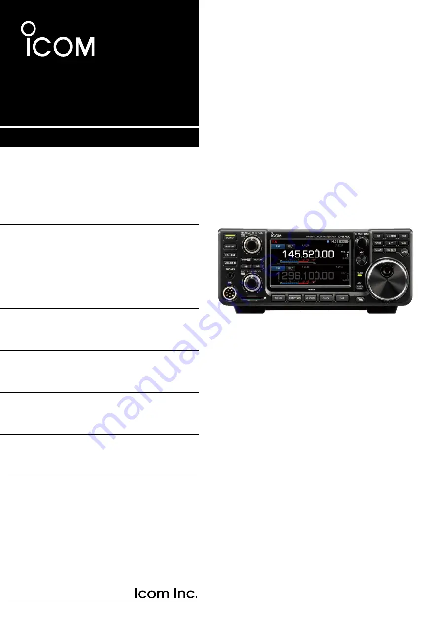
|9700
VHF/UHF ALL MODE TRANSCEIVER
Page 1: ...BASIC MANUAL 9700 VHF UHF ALL MODE TRANSCEIVER...
Page 2: ...IP3 performance When a weak signal is received adjacent to strong interference the AD converter is optimized against signal distortion A 4 3 inch touch panel color display Multi function control for...
Page 3: ...ons at the end of their working life Do not dispose of these products as unsorted municipal waste Dispose of them according to the laws in your area FCC INFORMATION Icom is not responsible for the des...
Page 4: ...y damage it Tablet PC operations such as flick pinch in and pinch out cannot be performed on this touch screen D D Touch screen maintenance If the touch screen becomes dusty or dirty wipe it clean wit...
Page 5: ...Display Type SET screen Rotate Push The Advanced and Basic manuals are described in the following manner Quotation marks Used to indicate icons setting items and screen titles displayed on the screen...
Page 6: ...D D Changing the Tuning Step 3 4 D D About the 1 MHz Step Tuning function 3 4 D D About the 1 Hz step Fine Tuning function 3 4 D D About the 1 4 Tuning function 3 5 D D About the Auto Tuning Step func...
Page 7: ...Loop test procedure 7 2 Satellite operation 7 3 Satellite memories 7 3 D D Satellite memory screen 7 3 Set mode description 8 1 8 SET MODE 8 1 Tone Control TBW 8 2 Function 8 2 My Station 8 5 DV DD S...
Page 8: ...ce where the transceiver may suddenly move or fall This could cause an injury or damage the transceiver R WARNING NEVER operate the transceiver during a lightning storm It may result in an electric sh...
Page 9: ...select the Main or Sub band z z Hold down M S upper for 1 second to toggle between the Main and Sub band s frequency and operating modes z z Hold down OFF lower for 1 second to turn the Dualwatch fun...
Page 10: ...lected VFO s frequency mode and filter settings to the other VFO 7 PASSBAND TUNING CONTROL KEY PBT p 4 3 Enables MULTI to adjust the Passband Tuning Control PBT 8 kHz TUNING STEP M CH KEY kHzM CH p 4...
Page 11: ...KEY JACK KEY p 2 2 Connects to a straight key paddle or an external electronic keyer with 3 5 mm 1 8 stereo plug i CI V REMOTE CONTROL JACK REMOTE p 2 2 Connects to a PC or other transceiver for exter...
Page 12: ...ed while the transceiver and the optional RS BA1 are connected through a LAN cable for Remote control operation i SD CARD ICON p 6 1 Displayed when an SD card is inserted and blinks while accessing th...
Page 13: ...p 3 9 Displayed while the Auto Gain Control AGC is ON 6 AFC 1 4 ICON p 8 5 is displayed while the Auto Frequency Control AFC is ON is displayed while the 1 4 Tuning function is ON p 3 5 7 MULTI FUNCTI...
Page 14: ...OFF OFF OFF OFF ON ON ON BKIN F BKIN COMP 2 TONE 2 OFF OFF DTCS DTCS T TSQL R ON TONE DTCS T TONE T TSQL R TSQL TONE T DTCS R D SQL 2 TBW 1 4 MONI 2 OFF WIDE OFF OFF DSQL MID ON ON CSQL NAR DUP 2 EXP...
Page 15: ...nus The function is displayed in the upper right edge of the screen 1 You can independently enable MULTI to adjust the function for the MAIN and SUB bands 2 On the Multi function menus touch the item...
Page 16: ...0 to 9 space 70 VOICE VOICE TX RECORD A to Z a to z 0 to 9 space _ 16 CS UR R1 R2 A to Z 0 to 9 space 8 DV DD MEMORY Your Call Sign NAME A to Z a to z 0 to 9 space _ 16 CALL SIGN A to Z 0 to 9 space 8...
Page 17: ...MENU by pushing QUICK D DEntering and editing Clears the entered character Selects alphabet mode or number mode Enters a space Selects the character type Saves the entry Cancels entry and returns to t...
Page 18: ...nd You can also open the QUICK MENU by touching this key Opens the QUICK MENU 3 Select Edit Name Rotate Push Opens the MEMORY NAME screen 4 Touch and then touch D 5 Touch again and then touch X 6 Touc...
Page 19: ...ation for the transceiver that allows adequate air circulation free from extreme heat cold or vibration and other electromagnetic sources Never place the transceiver in areas such as Temperatures belo...
Page 20: ...ents into the desired channel in the MEMORY list Call channel mode Call channels or Main channel are used to call on an often used frequency A Call channel is assigned on each band Selecting the VFO m...
Page 21: ...r OFF Selecting the Main and Sub bands The IC 9700 has 2 identical receivers Main and Sub The Main band is displayed on the upper half of the screen and the Sub band is displayed on the lower half L S...
Page 22: ...K PSK31 JT65B and FT8 L When a data mode is selected you can mute the input from the microphone MENU SET Connectors MOD Input DATA MOD Selecting the operating band Do the following steps to change the...
Page 23: ...on the microphone the frequency changes in 1 MHz steps D DChanging the Tuning Step When the Tuning Step function is ON you can change the tuning steps for each operating mode 1 Select the desired ope...
Page 24: ...ry with the most significant digit Opens the BAND STACKING REGISTER screen 2 Touch F INP LTo clear the entry touch CE L To clear the entry and return to the previous screen push EXIT 4 Touch ENT to se...
Page 25: ...Opens the BAND STACKING REGISTER screen 3 Touch F INP Opens the F INP screen 4 Enter a Memory channel number Example 10 L If you want to set the Program Scan Edge channel or Call channel enter between...
Page 26: ...p 2 Select ON User or ON User TX Limit L If you select ON User TX Limit you can limit transmission to within the entered frequency range 3 Select User Band Edge Rotate Push Rotate Push Editing a Band...
Page 27: ...1 Entry example 4 3 0 1 ENT Rotate Push 4 Enter the upper band edge frequency then touch ENT Example 439 9 Entry example 4 3 9 9 ENT The entered band edge is saved and returns to the previous screen D...
Page 28: ...l reset all the band edges to their initial settings All entered settings will be deleted 1 Open the User Band Edge screen 2 Touch any band edge for 1 second L The new band edge will be inserted above...
Page 29: ...r 1 second to turn the Dial Lock function ON or OFF During Split Frequency operation the Split Lock function may be turned ON p 4 10 MENU SET Function Lock Function Hold down Rotate AF RF SQL outer to...
Page 30: ...PTT on the microphone and speak at your normal voice level In the SSB mode touch the TX meter to select the ALC meter and rotate MULTI to adjust the microphone gain until the meter reading swings bet...
Page 31: ...RIT frequency to 0 00 by holding down MULTI for 1 second L You can add the frequency shift to the operating frequency by holding down RIT for 1 second 3 After communicating push RIT to turn the RIT fu...
Page 32: ...CTION Opens the FUNCTION screen 3 Touch AGC for 1 second Opens the AGC SSB screen 4 Touch FAST MID or SLOW Example MID 5 Rotate MAIN DIAL to set the time constant 6 To close the AGC SSB screen push EX...
Page 33: ...ld down MULTI for 1 second to clear the PBT setting 3 Repeat steps 1 and 2 to adjust the shift value for PBT2 LInformatio L To narrow the IF passband width shift PBT1 and PBT2 to the opposite directio...
Page 34: ...Hz FIL 2 1 2 kHz FIL 3 500 Hz CW FIL 1 1 2 kHz 50 Hz to 500 Hz 50 Hz 600 Hz to 3 6 kHz 100 Hz FIL 2 500 Hz FIL 3 250 Hz RTTY FIL 1 2 4 kHz 50 Hz to 500 Hz 50 Hz 600 Hz to 2 7 kHz 100 Hz FIL 2 500 Hz F...
Page 35: ...various type of noise you can adjust the attenuation level and blanking depth and width in the NB menu 1 Hold down NB for 1 second Turns ON the Noise Blanker and opens the NB menu 2 Touch the item to...
Page 36: ...unctions Auto Notch automatically attenuates beat tones tuning signals and so on It can be used in the SSB AM and FM modes Manual Notch attenuates beat tones tuning signals and so on by manually adjus...
Page 37: ...ONITOR to the clearest audio output between 0 and 100 while speaking at your normal voice level NOTE When using the VOX function turn OFF the Monitor function Otherwise the transmitted audio will echo...
Page 38: ...ction meter to display the ALC meter L Touching the Multi function meter sets the meter to Po SWR ALC COMP VD or ID 6 Push MULTI to display the Multi function menu 7 Touch MIC GAIN and then adjust it...
Page 39: ...FO and activate the Split function 1 Set VFO A s receive frequency and operating mode Example 146 540 MHz in the USB mode 2 Hold down SPLIT for 1 second The Quick Split function is turned ON and the V...
Page 40: ...th to WIDE MID or NAR The transmit filter widths are set to the following values by default SSB WIDE 100 Hz to 2900 Hz SSB MID 300 Hz to 2700 Hz SSB NAR 500 Hz to 2500 Hz SSB D 300 Hz to 2700 Hz L You...
Page 41: ...addle by default You can select the keyer type on the CW KEY SET screen p 4 12 5 To close the BKIN menu push EXIT Full Break in operation In the Full Break in mode the transceiver automatically transm...
Page 42: ...screen KEYER screen 4 Select the desired item to set KEYER MEMORY edit menu You can edit the Keyer memories M1 to M8 001 SET CW KEY SET EXIT KEYER 001 contest number menu You can set the following ite...
Page 43: ...quencies in the Fixed Edges item on the SCOPE SET screen by touching EXPD SET for 1 second HOLD Touch Sets the Hold function to ON or OFF HOLD and the Marker are displayed Freezes the current spectrum...
Page 44: ...e frequency is outside the higher edge When the frequency goes further away Scope Out of Range is displayed 2 5 kHz 2 5 kHz Center mode 145 800 MHz 146 000 MHz Fixed mode D DTouch screen operation Whe...
Page 45: ...lay and oscilloscope waveform color 1 Display the AUDIO SCOPE screen MENU AUDIO 2 Touch SET 3 Touch to select the item to set Example FFT Scope Waveform Type 4 Touch the option to set L See below for...
Page 46: ...the important data onto your PC Icom will not be responsible for any damage caused by data corruption on an SD card You can save the following data onto the card Data settings and Memory channel conte...
Page 47: ...d from the transceiver L Push in the SD card until a click sounds to unlock the card and then pull it out 5 To close the SD CARD screen push EXIT several times When the transceiver is OFF You can remo...
Page 48: ...ing options Example CI V Address is displayed left side of the selected option L The Set mode settings and Memory channel contents are always loaded 5 Touch Load 6 Touch YES or NO Keep SKIP settings i...
Page 49: ...tting 2 Touch the file to delete for 1 second NOTE Deleted data from a card cannot be recalled Before deleting any data back up the card data onto your PC 3 Touch Delete LTo delete all files touch Del...
Page 50: ...nsceiver 1 Open the IMPORT EXPORT screen MENU SET SD Card Import Export 2 Touch Import 3 Touch the data to import Example Your Call Sign 4 Touch the CSV file to import TIP To import a repeater list se...
Page 51: ...Example Your Call Sign 4 Touch New File L The file name is automatically set in the following format Your yyyymmdd_xx yyyy Year mm month dd day xx serial number Rpt is displayed for a repeater list an...
Page 52: ...st folder Saves the Repeater List in the csv format to import YourMemory folder Saves the Your Call Sign Memory in the csv format to import Decode folder Saves the RTTY decode log Rtty folder Saves th...
Page 53: ...ons or on web sites Satellite tracking software is also convenient D DSetting the satellite VFO 1 Touch MAIN The Main band is selected Key Function MAIN Touch to select the Main band Downlink frequenc...
Page 54: ...onfirm the communication status between your station and the satellite By transmitting your voice Example your call sign check the received audio L The beacon frequency drifts Doppler effect Rotate MA...
Page 55: ...ffect rotate MAIN DIAL to tune to the frequency When you use beam antennas you may need critical adjustment of the antenna direction especially when communicating through satellites in low orbits The...
Page 56: ...r to scroll through the items L You can also rotate MULTI to scroll through the items 5 Touch the item to open the item s setting screen or to open its next tree level LTo go back the previous tree le...
Page 57: ...p to the specified level OFF Does not limit the volume level ON Limits the volume level Beep Confirmation Default ON Turns the Confirmation beep ON or OFF OFF Turns the function OFF for silent operati...
Page 58: ...green OFF Turns OFF the function ON Turns ON the function MENU SET Function Time Out Timer Default OFF Sets the Time out Timer to OFF 3 5 10 20 or 30 minutes to prevent an accidental prolonged transm...
Page 59: ...H Default ON Turn the RX CS Speech function ON or OFF S Level SPEECH Default ON Turns the S meter level announcement ON or OFF OFF The operating mode and the operating frequency are announced when you...
Page 60: ...he keyboard entry type to Ten Key or Full Keyboard Full Keyboard Layout Default English Selects the on screen keyboard layout between English German and French My Station MENU SET My Station My Call S...
Page 61: ...mit data Auto When data is input from a PC through the DATA jack the transceiver automatically transmits it MENU SET DV DD Set DV Fast Data Fast Data Default OFF Selects whether or not to use the DV F...
Page 62: ...where the two other stations are communicating with call sign squelch enabled OFF Turns OFF the function ON Turns ON the function L The BK function is automatically turned OFF when transceiver is turn...
Page 63: ...is made on an SD card and saved in the csv format LThis function requires an SD card User supplied OFF The RX History Log function is OFF ON The transceiver makes a DV mode s receive history log on t...
Page 64: ...West longitude My Altitude 50 5 50 5 Your altitude unit m Records to one decimal place RPT Call Sign JP3YHJ JP3YHJ A Repeater call sign DV mode only TX Call Sign CQCQCQ Blank TX Call sign DV mode only...
Page 65: ...itude if sent unit m Records to one decimal place SSID A Caller s SSID if sent 0 1 to 15 A to Z D PRS Symbol Car Icon Converts to text None Code Course 123 Caller s course unit degree Speed 23 5 Calle...
Page 66: ...ut from the left side and the SUB band audio is output from the right side When the SUB band is not displayed The MAIN band audio is output from the left and right side MENU SET Connectors ACC AF IF O...
Page 67: ...fault 50 Sets the modulation input level of each interface DATA OFF MOD Default MIC ACC DATA MOD Default ACC In the SSB AM or FM mode selects the connector s to input the modulation signal when the da...
Page 68: ...s is not output ON The status is output When you change a setting on the transceiver the same change is automatically set on other connected transceivers or receivers and vice versa CI V USB LAN REMOT...
Page 69: ...ption dialog after holding down POWER for 1 second Shutdown only Shut down the IC 9700 when you turn it OFF Standby Shutdown Displays the Standby Shutdown option dialog when you turn it OFF Network ME...
Page 70: ...ftware when you remotely control the IC 9700 Display MENU SET Display LCD Backlight Default 50 Sets the LCD backlight brightness Display Type Default A Sets the display type to A or B Display Font Def...
Page 71: ...splay the caller s position data ON Automatically displays the caller s position data TX Call Sign Display Default Your Call Sign Select whether or not to display My or Your call sign while transmitti...
Page 72: ...o English Display Language is not displayed When you set the system language of the transceiver to Japanese the IC 9700 has the capability to display both English and Japanese characters HOWEVER if yo...
Page 73: ...ime nist gov Sets NTP server address GPS Time Correct Default Auto Select whether or not the time data is automatically corrected by a received GPS sentence MENU SET Time Set UTC Offset Default 0 00 S...
Page 74: ...creen Calibration Touch to adjust the touch screen LSee the Advanced Manual for details MENU SET Others Reset Partial Reset Resets operating settings to their default values VFO frequency VFO settings...
Page 75: ...ction Using this function you can manually synchronize the internal clock by accessing the time management server 1 Open the DATE TIME screen The NTP Network Time Protocol function synchronizes the in...
Page 76: ...with the transceiver The fuses are installed in the DC power cable and in the inside circuitry to protect the transceiver DC power cable fuses ATQ 25 A Circuitry fuse ATC 5 A 1 2 3 ATQ 25 A fuse 1 Rem...
Page 77: ...ory contents GPS memory contents Repeater list contents Network settings REF Adjust Fixed Edges Allowed call sign list contents After performing an All reset All reset clears all data and returns all...
Page 78: ...2 Remove the SD card from the master transceiver 3 Insert the SD card into the sub transceiver then turn ON the sub transceiver L The file name is automatically set in the following format Setyyyymmdd...
Page 79: ...loading options Example CI V Address is displayed left side of the selected option L The Set mode settings and Memory channel contents are always loaded 5 Touch Load 6 Touch YES or NO Load file is di...
Page 80: ...dot that is displayed on the screen A new dot appears in another position 4 Repeat step 3 L When the calibration is complete the transceiver returns to the OTHERS screen Touch the displayed dot TIP Wh...
Page 81: ...The antenna is defective or the coaxial cable is defective Repair the problem and then reconnect the antenna p 13 3 You are using an antenna that is not suitable for the band you have selected Connect...
Page 82: ...s set Set at least 2 memory channels Select memory scan does not start No or only 1 memory channel is designated as a Select channel Designate at least 2 memory channels as Select channels for the sca...
Page 83: ...le and try again After your call the repeater replies RX or RPT and the access repeater s call sign Your own call sign MY has not been set Set your own call sign MY Your own call sign MY has not been...
Page 84: ...et in FROM Access Repeater has no Gateway Check the repeater settings L is displayed on the LCD While receiving through the internet some packets may be lost due to network error poor data throughput...
Page 85: ...Operating modes USB LSB J3E CW A1A RTTY F1B AM A3E FM F2D F3E DV F7W and DD F1D Number of memory channels 297 channels 99 channels 3 bands Number of program scan channels 18 channels 6 channels 3 band...
Page 86: ...SB Digital PSN modulation FM Digital Reactance modulation AM Digital Low power modulation DV Digital GMSK modulation DD Digital GMSK modulation Spurious emission Harmonics Less than 63 dB 144 MHz band...
Page 87: ...dB V emf FM BW 7 kHz 60 Modulation 12 dB SINAD Less than 6 dB V emf Selectivity Filter SHARP SSB BW 2 4 kHz More than 2 4 kHz 3 dB Less than 3 6 kHz 60 dB CW BW 500 Hz More than 500 Hz 3 dB Less than...
Page 88: ...19 microphone The same as supplied SM 50 desktop microphone Dynamic microphone with UP DOWN switches PS 126 dc power supply Output voltage 13 8 V DC Maximum output current 25 A SP 34 eXternal speaker...
Page 89: ...push in the center part of the rubber feet 2 Attach the carrying handle using the supplied screws as shown to the right NOTE Before mounting the MB 118 carefully read PRECAUTIONS p vii and decide the...
Page 90: ...the transceiver When this pin goes to ground the transceiver transmits Input voltage RX Input voltage TX Current flow 2 20 V 0 5 0 8 V Maximum 20 mA The pin goes low when the transceiver transmits Ou...
Page 91: ...r remote control by CI V commands Cloning the setting data using the CS 9700 software Remotely controlling using optional RS BA1 L You can change the signal output type and output level MENU SET Conne...
Page 92: ...com PINe PINy 1 5 k 5 1 5 k 5 2 2 k 5 4 7 k 5 S1 S2 S3 S4 1 2 3 4 5 6 7 8 MIC External keypad Front panel view MIC connector NOTE Pin 1 outputs 8 V DC power for Icom microphones L Memory RT5 RT8 RTTY...
Page 93: ...CT INCIDENTAL SPECIAL EXEMPLARY OR CONSEQUENTIAL DAMAGES INCLUDING BUT NOT LIMITED TO PROCUREMENT OF SUBSTITUTE GOODS OR SERVICES LOSS OF USE DATA OR PROFITS OR BUSINESS INTERRUPTION HOWEVER CAUSED AN...
Page 94: ...V DD Set Set mode 8 6 E Electronic Keyer function 4 12 Entering Example 1 10 Keyboard 1 9 Exporting a CSV 6 6 F Features i FFT scope 5 3 Filter IF filter 4 4 Notch Filter 4 6 Transmit filter width 4 1...
Page 95: ...mode 8 18 Set mode 8 1 Connectors 8 11 Display 8 15 DV DD Set 8 6 Function 8 2 My Station 8 5 Network 8 14 Others 8 19 QSO RX Log 8 8 SD Card 8 18 Time Set 8 18 Tone Control TBW 8 2 Specifications 11...
Page 96: ...1 1 32 Kamiminami Hirano ku Osaka 547 0003 Japan A7508H 1EX Printed in Japan 2019 Icom Inc Feb 2019...