


9
AND THE RETURN AIR PLENUM.
THE RETURN AIR PLENUM MUST
BE PERMANENTLY ENCLOSED.
NEVER USE A DOOR AS A PART OF
THE RETURN AIR PLENUM. THE
FLOOR OR PLATFORM MUST
PROVIDE SOUND PHYSICAL
SUPPORT OF THE FURNACE,
WITHOUT SAGGING, CRACKS,
GAPS, ETC., AROUND THE BASE AS
TO PROVIDE A SEAL BETWEEN
THE SUPPORT AND THE BASE.
FAILURE TO PREVENT PRODUCTS
OF COMBUSTION FROM BEING
CIRCULATED INTO THE LIVING
SPACE CAN CREATE POTENTIALLY
HAZARDOUS CONDITIONS,
INCLUDING CARBON MONOXIDE
POISONING THAT COULD RESULT
IN PERSONAL INJURY OR DEATH.
DO NOT, UNDER ANY
CIRCUMSTANCES, CONNECT
RETURN OR SUPPLY DUCTWORK
TO OR FROM ANY OTHER HEAT
PRODUCING DEVICE SUCH AS A
FIREPLACE INSERT, STOVE, ETC.
DOING SO MAY RESULT IN FIRE,
CARBON MONOXIDE POISONING,
EXPLOSION, PERSONAL INJURY
OR PROPERTY DAMAGE.
BLOWER AND BURNERS MUST
NEVER BE OPERATED WITHOUT
THE BLOWER DOOR IN PLACE.
THIS IS TO PREVENT DRAWING
GAS FUMES (WHICH COULD
CONTAIN HAZARDOUS CARBON
MONOXIDE) INTO THE HOME THAT
COULD RESULT IN PERSONAL
INJURY OR DEATH.
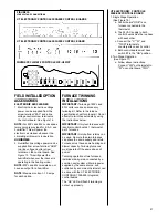
UPFLOW UNITS
1. Set furnace in place and connect the
return duct or return air cabinet to
unit. Make the connection air-tight to
prevent entraining combustion
gases from any adjacent fuel-
burning appliances. Unit return air
may be connected on the sides or
bottom of the return air
compartment.
a. Openings in the side must be cut
out the full width of the knockouts
on the unit. If using side return air,
THE BOTTOM base plate must
be installed
.
NOTE:
Where the maximum
airflow is 1800 CFM or more, both
sides or the bottom must be used
for return air.
b. If using bottom return air, place
furnace over return air plenum and
seal furnace bottom to return air
plenum.
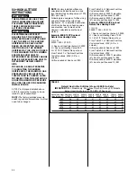
A SOLID METAL BASE PLATE, (SEE
TABLE 1) MUST BE IN PLACE
WHEN THE FURNACE IS
INSTALLED WITH SIDE OR REAR
AIR RETURN DUCTS. FAILURE TO
INSTALL A BASE PLATE COULD
CAUSE PRODUCTS OF
COMBUSTION TO BE CIRCULATED
INTO THE LIVING SPACE AND
CREATE POTENTIALLY
HAZARDOUS CONDITIONS,
INCLUDING CARBON MONOXIDE
POISONING OR DEATH.
2. If summer air conditioning is desired,
position the indoor coil on the top of
the unit. Insure that no air can
bypass this coil.
3. Connect the supply air plenum to the
furnace plenum opening.
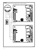
DOWNFLOW UNITS
THE DOWNFLOW FURNACE
DESIGN IS CERTIFIED FOR
INSTALLATION ON A NON-
COMBUSTIBLE FLOOR. IF
INSTALLED ON A COMBUSTIBLE
FLOOR, USE THE SPECIAL BASE
SPECIFIED ON THE FURNACE
CLEARANCE LABEL. FAILURE TO
INSTALL THE SPECIAL BASE MAY
RESULT IN FIRE, PROPERTY
DAMAGE, PERSONAL INJURY OR
DEATH. THIS SPECIAL BASE IS
SHIPPED FROM THE FACTORY AS
AN ACCESSORY.
1. Position the unit over the supply air
plenum and connect.
a. If installing on a combustible floor
and not using an evaporator
coil box,
install the special
combustible floor base.
See Figure 4.
b. If summer air conditioning is
desired, position the indoor coil on
the bottom of the unit. Insure that
no air can bypass this coil.
2. Connect the return air ducting to the
return air opening at the top of the
unit. Make the connection air tight to
prevent entraining combustion
gases from an adjacent fuel-burning
appliance.
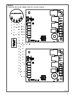
HORIZONTAL UNITS
1. Unit can be mounted left or right
side airflow configuration.
2. Position the unit on adequate
supports or by using support
brackets (see Figure 1) and connect
supply plenum.
3. If summer air conditioning is desired,
position the indoor coil on the supply
air side of the unit. Insure that no air
can bypass this coil.
4. Secure the four angle brackets
shipped with the unit to the return air
opening. See Figure 5. Connect the
return air ducting to the return air
opening at the top of the unit. Make
the connection air tight to prevent
entraining combustion gases from
an adjacent fuel-burning appliance.
NOTE:
Do not block furnace access
with support rods. Maintain clearances
recommended in Figure 2. Allow
enough space for proper service,
maintenance or replacement of the
heat exchanger and blower assembly.
FIGURE 4
COMBUSTIBLE FLOOR BASE
WARNING
!
WARNING
!
WARNING
!