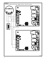
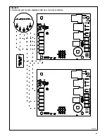
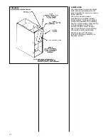
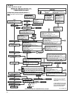
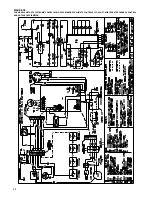
Iceco 80LJ SERIES Installation Instructions Manual Download Page 36

36

FIGURE 28

TROUBLESHOOTING FLOWCHART

GO TO

E

WARNING

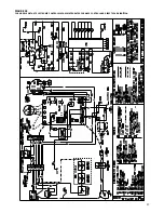
INTEGRATED FURNACE CONTROL (IFC)

TROUBLESHOOTING GUIDE

HAZARDOUS VOLTAGE

LINE VOLTAGE

CONNECTIONS

DISCONNECT POWER BEFORE SERVICING.
SERVICE MUST BE BY A TRAINED, QUALIFIED
SERVICE TECHNICIAN.

NOTE: Most failures are not due to the IFC. Double check all other
possibilities, including the ground connection, before replacing the IFC.

NOTE: Always verify gas valve inlet and outlet gas
pressure.

KEY TO ABBREVIATIONS
IBM = Indoor Blower Motor
IDM = Induced Draft Motor
IFC = Integrated Furnace Control
PS = Pressure Switch(es)
SE = Spark Electrode
HSI = Hot-Surface Ignition
DSI = Direct-Spark Ignition

FLAME (AMBER) LED CODES
OFF = No Flame Present
RAPID BLINK = Unexpected Flame
SLOW BLINK = Marginal Flame Sense
STEADY ON = Normal Flame Sense

BLINK CODES (GREEN LED)
1 Blink - Soft lockout

Reset System power and
start over from beginning

2 Blinks - PS Circuit open

go to point “F.”

3 Blinks - Limit circuit open

go to point “D.”

4 Blinks - PS Circuit closed

Go to point “G.”

5 Blinks - Twin Fault (Optional)

*Go to point “H.”

1) Set FAN switch to “AUTO”
2) Set thermostat to call for heat (set temp. differ-

ential to greater than 10°F

Does the IDM Energize?

IDM Runs for 30 sec. pre-purge?

Spark Ignitor Electrode (SE) Energizes

or HSI Ignitor Glowing? 

Does Main Burner Light and stay lit?

Is the gas valve energized?

PS dropping out?

Check IFC*

Does IBM start on heat speed 20 seconds

after burners light?

Does main burner remain lit until

heat call ends?

Does thermostat maintain reasonable room 

temperature near setpoint?

Set thermostat to off position (W to C = ØV)

Does gas valve shut off immediately?

Does IDM shut off after ten second post-purge?

Does IBM shut off after a max. of 3 min?

END

Heat-mode troubleshooting

“POWER” LED ON?

24V on W to IFC?

Is “STATUS” LED blinking,

steady-on, or off?

Check IFC*.

Check IFC*.

Does IDM run
indefinately.

Does IDM Run for 60 sec. and then off for Five minutes

- Check thermostat in “heat” mode,
battery, wire, and connections.

SEE BLINK CODES

- Check 24V at IFC.
- Check Fuse.
- Check Door Switch and Line Power.
- Check Transformer.
- Check Breaker.

- Check PS contacts
- Check wires for short.
- Check IFC*.
- Check switches and hoses for

water or moisture

- For Twinned units, check that both IFCs are set for “TWIN” and wires

are connected between “TWIN” terminals.

- Check IFC*.
- For twinned units, ensure transformers are in phase.

(if out of phase, flame LED will be dim).

- For non-twinned units, ensure “TWIN” is in the single (OFF) position.
- For Twinned units – ensure both IFC‘s have same part number.

- Check PS, PS Hoses, and wires.
- Check for blocked vent, excessive vent length or elbows, or

blocked heat exchanger.

- Check IDM wired correctly.
- Ensure against excessive wind, which can open pressure switch.
- If downflow 90+, check aux. limit – shoud be closed
- Check for intermittent P.S. operation.
- Check switches and hoses for water or moisture.

- Check gas supply and manifold pressure.
- Ensure L1 and Neutral not swapped on IFC and junction box.
- Check SE alignment.
- Check orifice or other restrictions to gas flow.
- Check flame sense rod (clean with sandpaper).
- Check flame carry over.

- Check wires, continuity, and connection between IFC and gas valve.
- Ensure 24 V between appropriate pins on connector of IFC.
- Ensure manual switch on valve is in the “ON” position.
- 90+ check aux. limit open? Should be closed
- 90+ upflow models – check drain pressure switch between IFC and

gas valve – should be closed – replace drain pressure switch if drain
is not blocked or clear drain if blocked.

- Did a pressure switch open during ignition trial? If yes, go to  F
- Did a limit open during ignition trial? If yes, go to  D

- Check line voltage between “HEAT” and “NEUTRAL” on IFC.
- Check wires, connections, and continuity between   IFC and IBM.
- Check IBM capacitor.
- Check IBM.

CHECK:
- grounding on IFC and unit.
- check for proper polarity between L1 & neutral.
- flame sense rod (clean if necessary).
- wire continually between flame sense rod and appropriate pin of

connector on IFC

- flame carries across all burners, and all burners stay lit.

CHECK:
AIRFLOW - ensure no restrictions, such as dirty filter, dampers, closed registers, etc.
LIMITS - ensure good wire and connections between IFC and all limits. Make sure
limits are not open when circulating air temperature is within a specified range.
ROLLOUTS - ensure rollouts or overtemperature limits do not need to be reset. Make
sure no flame rollout in burner compartment due to blocked flu or heat exchanger.
OVERFIRE - ensure furnace is not overtemperature (temp rise is above stated range).
Check gas valve, proper orifice size, gas pressure, etc.

Is Limit circuit or IDM wire through aux. limit open or
opening and closing?
Note: IFC Status LED should be blinking a Fault Code 3.

Is the IFC sensing a good flame: NOTE:
Flame sense light should be steady-on
when burners are lit. If flame LED blinking,
or off, flame sense is low or absent.

Ensure thermostat is properly placed and not improperly affected by
registers, fans, sunlight, heat through walls, pipes, or wires in walls.

- Check heat anticipator setting. Furnace may need an isolation relay.
- Check installation instructions under section titled “Isolation Relay” for

details.

- Verify correct furnace sizing.

NOTE: If IFC goes into lockout (“STATUS LED will blink code “1”), shut
off main power to unit, wait 30 seconds and then reset power.

PROBLEM

STILL

PRESENT

“STATUS” LED

BLINKING

“FLAME” LED BLINKING
OR STEADY ON

If “E” did not
resolve issue

Double check - Is W off at IFC?

(W to C = ØV?)

Voltage present at gas valve?

- Check gas valve.

SEE BLINK CODES

- Check IFC*.

Check IFC*.

*Most failures are not due to the IFC. Double
check all other possibilities, including the
ground connection or wire connections, before
replacing the IFC.

Ensure TSTAT is not in “FAN” position.
Is “STATUS” LED blinking?
Is “FLAME” LED blinking or steady-on?

**System will attempt to light 4 times. Voltage
is present at gas valve for only 7 seconds dur-
ing each trial for ignition. The entire system will
go into a 1 hour lockout after 4 attempts. The
main blower and IDM will run 180 seconds
between 2nd and 3rd ignition attempts.

- Check line voltage at IDM.
- Check wires and connections between IDM and IFC.
- Ensure line voltage on IDM pins of IFC connector.
- Check IDM capacitor (90+ only).

CHECK BLINK CODES
- Check for open limit or limit circuit.
- Check for intermittent PS operation.
- Check for vent restrictions.
- Ensure vent lengths not excessive or

too small diameter.

- Check for blocked heat exchanger.

FOR SPARK IGNITION
- Check SE wire & connections.
- Clean SE with sandpaper. Replace SE if necessary.
- If problem persists, check IFC*.
- Check SE gas and proper SE ground.
- Check SE wire for spark arcing to metal before electrode.

FOR HOT SURFACE IGNITION
- Check ignitor connected.
- Check ignitor wires.
- Check ignitor resistance. If open circuit, low or high resistance, replace.
- Check ignitor for fractures or cracking
- Check ignitor placement.
- If problem persists, check IFC*.

START

REPEAT THIS PROCEDURE UNTIL TROUBLE-FREE OPERATION IS OBTAINED.

NO

NO

NO

If “

I

” did not

resolve issue.

NO

NO

NO

NO

NO

NO

NO

NO

NO

NO

NO

NO

NO

NO

NO

BLINKING

YES

YES

YES

YES

YES

YES

YES

YES

YES

YES

YES

YES

YES

YES

YES

YES

YES

YES

STEADY-ON

I

D

F

H

E

G

YES

NO

YES

PREPURGE

IGNITION TRIAL

IBM “ON” DELAY

STEADY HEAT

END HEAT CALL

POST-PURGE

IBM “OFF” DELAY

STEADY OFF

NO

OFF

**

92-101654-01-00

GO TO

F

GO TO

I

Summary of Contents for 80LJ SERIES

Page 1: ...CTIONS FOR UPFLOW UPFLOW HORIZONTAL AND DOWNFLOW INDUCED DRAFT GAS FURNACES 80PJ AND 80LJ SERIES PROPOSITION 65 THIS PRODUCT CONTAINS CHEMICALS INCLUDING CARBON MONOXIDE KNOWN TO THE STATE OF CALIFORN...

Page 2: ...furnace ground to electrical panel DC microamp A flame signal hot surface ignition units Correct control voltage Measure and set heat anticipator amperage Air conditioning low voltage wires connected...

Page 3: ...fects such as fiberglass insulation lead in brass and combustion products from natural gas All new equipment shipped for sale in California will have labels stating that the product contains and or pr...

Page 4: ...N PLACE SET FURNACE INPUT RATE AND TEMPERATURE RISE PER RATING PLATE MARKING MEANS FOR PROVIDING OUTDOOR AIR REQUIRED FOR COMBUSTION RETURN AIR TEMPERATURE MAINTAINED BETWEEN 55 F 13 C AND 80 F 27 C A...

Page 5: ...is unit when installed For attic or crawl space installation horizontal furnaces may be installed on combustible wood flooring or by using support brackets See Figure 1 6 IMPORTANT If installing in a...

Page 6: ...RIZONTAL MODELS TOP LEFT SIDE FRONT RIGHT SIDE BOTTOM 24 1 2 26 13 16 26 5 8 24 11 32 24 11 32 19 32 9 16 24 7 16 28 1 16 26 5 8 14 3 8 11 1 2 34 1 5 8 DIA 23 15 20 D 7 8 DIA 7 8 DIA 19 32 19 32 3 4 1...

Page 7: ...15 5 8 23 5 8 0 0 0 1 3 6 140 lbs 15 24 1 2 23 11 32 15 5 8 23 5 8 0 0 0 1 3 6 150 lbs TOP BOTTOM 24 1 2 19 3 4 C A B D LOW VOLTAGE GAS CONNECTION ELECTRIC CONNECTION E 26 5 8 26 13 16 6 3 16 20 3 8 2...

Page 8: ...uding evaporator coil if used of the entire system should not exceed 0 5 w c Be sure to have adequate space for unit filter IMPORTANT Some high efficiency filters have a greater than normal resistance...

Page 9: ...NTO THE LIVING SPACE AND CREATE POTENTIALLY HAZARDOUS CONDITIONS INCLUDING CARBON MONOXIDE POISONING OR DEATH 2 If summer air conditioning is desired position the indoor coil on the top of the unit In...

Page 10: ...unted in a closet the door must be closed when making this check of the installation DO NOT reset the overtemperature switch without taking corrective action to assure that an adequate supply of combu...

Page 11: ...ht construction contemporary construction outside air may still be required for the furnace to operate and vent properly Outside air openings should be sized the same as for a confined space FIGURE 7...

Page 12: ...uare inch for each 2000 BTUH of total input rating for all equipment in the enclosure see Figure 8 Here are typical duct sizes FIGURE 8 OUTSIDE AIR USING A HORIZONTAL INLET OUTLET B Method 2 One perma...

Page 13: ...SI Z223 1 AND OR THE NATURAL GAS INSTALLATION CODE CSA B149 1 2 FOR PROPER INSTALLATION PRACTICES SINGLE WALL VENT CONNECTORS TO B 1 VENT OR MASONRY CHIMNEYS MAY BE USED UNDER THE GUIDELINES OF THE NA...

Page 14: ...gher than any portion of a building within 10 feet 2 A type B 1 gas vent shall terminate at least 5 feet in vertical height above the highest connected equipment draft hood or flue collar 3 Must rise...

Page 15: ...operate a summer exhaust fan Close fireplace dampers 4 Follow the lighting instructions Place the appliance being inspected into operation Adjust the thermostat so the appliance will operate continuou...

Page 16: ...in size to prevent undue pressure drop and never smaller than the pipe size to the combination gas valve on the furnace Refer to Table 2 for the recom mended pipe size for natural gas and Table 3 for...

Page 17: ...ns The valve can be converted to use liquefied petroleum LP gas by replacing the pressure regulator spring with the conversion kit spring This LP kit spring allows the regulator to maintain the proper...

Page 18: ...the LP supplier adjust the line pressure at the regulator See Table 3 NOTE Depending on the amount of LP vapor and the outdoor ambient temperature the LP storage tank may require supplemental heat to...

Page 19: ...t off the manual main gas valve and remove the gas manifold 2 Replace the orifice spuds 3 Reassemble in reverse order 4 Turn the gas supply back on and check for proper operation and manifold pressure...

Page 20: ...available from the furnace manufacturer s Parts Department are acceptable Generally all thermostats that are not of the current robbing type are compatible with the integrated furnace control used NOT...

Page 21: ...with identical control boards 1 thermostat per 2 furnaces IMPORTANT Only bottom returns can be used No more than two furnaces can share the same supply and return Furnaces must have same heating and...

Page 22: ...22 I400 FIGURE 16 UT Electronic Controls 1028 928 CONTROL BOARD TWINNING CONNECTION SINGLE STAGE OPERATION a099201...

Page 23: ...23 FIGURE 17 UTEC 1028 928 CONTROL BOARD TWINNING CONNECTION TWO STAGE OPERATION a099301...

Page 24: ...lations are the best method Example 900 BTU ft3 Regional Natural Gas Heating Value I H Q 25000 900 27 78 ft 3 I Sea Level input per burner 25000 H Sea Level Heating Value 900 Q 27 78 ft 3 Natural Gas...

Page 25: ...23 000 22 000 21 000 20 000 19 000 18 000 17 000 16 000 All calculations are performed by using the first three columns of information only Before beginning any calculations determine the individual...

Page 26: ...site with manifold pressure adjustment to ensure that an actual 10 reduction in input rate is achieved Once this field adjustment has been made the label shown in Figure 18 rmust be affixed in a consp...

Page 27: ...don t light the system goes through another ignition sequence It does this up to four times 7 The main blower starts approximately 20 seconds after the burners ignite 8 When the thermostat W Heat Call...

Page 28: ...inducer run for 3 minutes before another ignition attempt is made NOTE The following applies only to units manufactured before third Quarter 2003 After a 30 second inter purge inducer runs continuous...

Page 29: ...to the furnace as possible FIGURE 21 TEMPERATURE RISE MEASUREMENT GAS FURNACE DIRECT DRIVE INSTRUCTIONS FOR CHANGING BLOWER SPEED DISCONNECT THE ELECTRICAL SUPPLY TO THE FURNACE BEFORE ATTEMPTING TO...

Page 30: ...30 BLOWER PERFORMANCE DATA 80LJ DOWNFLOW MODELS ONLY BLOWER PERFORMANCE DATA 80PJ UPFLOW HORIZONTAL MODELS...

Page 31: ...ck PRESSURE SWITCH This furnace is equipped with a normally open pressure switch that monitors pressure conditions within the furnace vent system during the heating cycle There are several reasons for...

Page 32: ...alified installer service agency or the gas supplier to prevent the possibility of overheating due to an accumulation of dust and dirt on the windings or on the motor exterior Air filters should be ke...

Page 33: ...or a filter base For systems with a return air filter grill or multiple filter grills can have a filter installed at each of the return air openings DO NOT DOUBLE FILTER THE RETURN AIR DUCT SYSTEM DO...

Page 34: ...D SIDE RETURN FIGURE 27 DOWNFLOW FILTER INSTALLATION FILTER ROD 45 24095 01 FILTER ROD SUPPORT ANGLE AE 60520 01 FILTER SUPPORT ANGLE SEE ANGLE DETAIL AE 61883 01 FILTER ROD SUPPORT ANGLE AE 60520 01...

Page 35: ...S OF THE VENT PIPE THE AREA AROUND THE FURNACE MUST BE KEPT CLEAR AND FREE OF ALL COMBUSTIBLE MATERIALS INCLUDING GASOLINE AND OTHER FLAMMABLE VAPORS AND LIQUIDS PLACEMENT OF COMBUSTIBLE MATERIALS ON...

Page 36: ...F Did a limit open during ignition trial If yes go to D Check line voltage between HEAT and NEUTRAL on IFC Check wires connections and continuity between IFC and IBM Check IBM capacitor Check IBM CHE...

Page 37: ...37 FIGURE 29 FOR MODELS WITH UT ELECTRONIC CONTROLS 1028 928 INTEGRATED FURNACE CONTROL AND DIRECT SPARK IGNITION...

Page 38: ...38 FIGURE 30 FOR MODELS WITH UT ELECTRONIC CONTROLS 1012 925 OR INVENSYS CLIMATE CONTROLS ICC H1MC7 01 INTEGRATED FURNACE CONTROL AND HOT SURFACE IGNITION...

Page 39: ...39...

Page 40: ...40 CM 0604 MANUFACTURED BY ICECO 5600 OLD GREENWOOD ROAD FORT SMITH ARKANSAS 72908...

Reviews: