


28
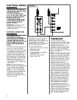
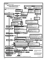
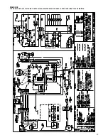
FIGURE 19
UT Electronic Controls 1012-925A
and Invensys Climate Controls
ICC-H1MC7
BLOWER OFF TIMINGS
OFF TIME
SWITCH 1
SWITCH 2
90 SEC.
OFF
ON
120 SEC.
OFF
OFF
160 SEC.
ON
OFF
180 SEC.
ON
ON
(TIMER IS
RED BLOCK
ON BOARD)
I335
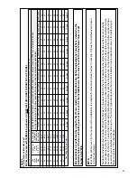
1. Each time the thermostat contacts
close, the induced draft blower
(inducer) begins a prepurge cycle.
2. The air proving negative pressure
switch(es) closes.
3.
30 seconds after the pressure
switch(es) close, the spark igniter
energizes.
The induced draft
blower operates for the complete
heating cycle.
4. After the spark igniter energizes,
t
he gas valve opens for a 8
second trial for ignition.
5. The igniter lights the gas burners.
6. After the gas valve opens t
he flame
sensor must prove flame ignition
for one second
using the process
of flame rectification. If the burners
don’t light, the system goes through
another ignition sequence. It does
this
up to four
times.
7. The main blower starts 20 seconds
after the burners ignite.
8. When the thermostat cycle ends,
the gas valve closes, the burners go
out, the induced draft blower stops
after a
10-second post-purge,
and
the negative pressure switch(es)
open.
9. The main blower continues until
timed off by the setting on the
integrated furnace control board.
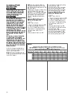
Sequence if the system doesn’t light
or doesn’t sense flame:
1. On a call for heat, the control runs
the inducer for 30 seconds to pre-
purge.
2. After the 30-second pre-purge, the
spark igniter energizes. The inducer
continues to run.
3. After the spark igniter energizes, the
gas valve opens for an 8-second
trial for ignition. The inducer
continues and the igniter stays
energized.
4. If flame is not sensed within 8
seconds after the gas valve opens,
the gas valve closes, the igniter de-
energizes and:
5. The inducer completes a 10-second
post-purge, the inducer stops, and
the control verifies that the pressure
switch has opened. Once the open
pressure switch is confirmed, the
control begins the next ignition cycle
by energizing the inducer for a pre-
purge of 30 seconds. After the pre-
purge, the igniter energizes and the
gas valve opens (inducer continues
to run). If no flame is sensed on the
second attempt, the control goes
into a “self-healing” mode, in which
the blower and the inducer run for 3
minutes before another ignition
attempt is made.
NOTE: The following applies only
to units manufactured before
third Quarter 2003:
After a 30-
second inter-purge (inducer runs
continuously), the igniter is
energized, and the gas valve opens
for 8 seconds. If flame is not sensed
in 8 seconds, the gas valve is
closed and the igniter de-energizes.
If no flame is sensed on this second
attempt, the control goes into a
“self-healing” mode, in which the
blower and inducer run for 3
minutes before another ignition
attempt is made.
6. The control attempts to ignite up to
four times (first attempt followed by
three retries). After the fourth
failure to ignite, the control goes
into a one-hour “soft-lockout”
during which the control will not
respond to the thermostat heat call
(W). The lockout can be reset by
shutting off main power to the
furnace for five seconds, or by
turning the heat call (W) from the
thermostat off and then back on.
7. The above sequence will repeat
after a one hour delay. It will
continue repeating until ignition is
successful or the call for heat is
terminated.
8. To reset the lock out, make and
break power either at the
thermostat or at the unit disconnect
switch for 5 to 10 seconds. It then
goes through another set of trials
for ignition.
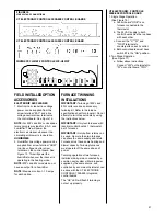
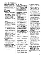
SETTING BLOWER TIMINGS
The UT Electronic Controls and
Invensys Climate Controls IFC’s
(integrated furnace controls) have four
quick connect terminals for connecting
the motor speed leads. These are:
1. FAN SPEED — motor runs on this
speed when the thermostat is in the
“FAN” position.
2. COOL — connect desired cooling
speed.
3. HEAT — connect desired heating
speed.
4. HEAT/COOL — connect desired
speed when heating and cooling
speed are the same.
NOTE:
This tap (heat/cool) not
available on 80PJ or 80LJ.
IMPORTANT:
Do not connect any
motor speeds to “HEAT” or “COOL” if
you use the “HEAT/COOL” terminal.
5. If heating and continuous speed
are the same, jump across “FAN”
and “HEAT” terminals.
NOTE:
This does not apply to 80PJ or
80LJ models because the heat tap
functions as the continuous fan tap as
well.
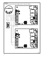
See Figures 18, 19 & 20 for instructions
for setting the blower “OFF” timings.
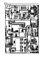
FIGURE 18
UT Electronic Controls 1028-928
BLOWER OFF TIMINGS
OFF TIME
SWITCH 1
SWITCH 2
90 SEC.
OFF
ON
120 SEC.
OFF
OFF
160 SEC.
ON
OFF
180 SEC.
ON
ON
TWIN
SINGLE
NOTE: SWITCH 3 IS USED FOR
TWINNING APPLICATIONS.
ON
I402
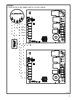
FIGURE 20
UT Electronic Controls 1012-925B
BLOWER OFF TIMINGS