


21
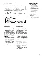
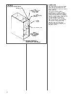
FIELD INSTALLED OPTION
ACCESSORIES
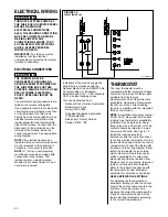
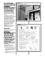
ELECTRONIC AIR CLEANER
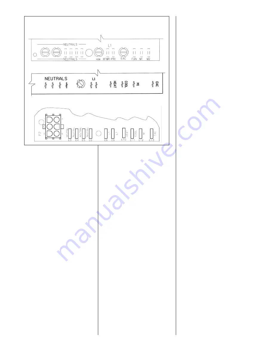
1. Electronic air cleaner line voltage
power can be supplied from the
screw terminal “EAC” and a line
voltage neutral screw terminal on
the control board. See Figure 15.
NOTE:
For 80PJ and 80LJ units spade
terms only are provided for E.A.C. and
humidifier. This will power the
electronic air cleaner whenever the
circulating air blower is in operation.
HUMIDIFIER
2. Humidifier line voltage power can be
supplied from screw terminal “HUM”
to a line voltage neutral screw
terminal on the control board. See
Figure 15. This will power the
humidifier whenever the inducer is
operating in the heating mode.
NOTE:
80PJ and 80LJ models do not
have an output for a humidifier.
NOTE:
Maximum current –1.0 amps
for each option.
FURNACE TWINNING
INSTALLATIONS
IMPORTANT:
Twinning of 80PJ and
80LJ units requires an accessory
twinning kit. Refer to the furnace
specification sheet for proper kit. Do not
attempt to twin these models by using
the instructions below.
IMPORTANT:
Only twin furnaces with
identical control boards. 1 thermostat
per 2 furnaces.
IMPORTANT:
Only bottom returns can
be used. No more than two furnaces
can share the same supply and return.
Furnaces must have same heating and
blower capacity. Twinning furnaces
must operate off the same phase of
power.
Twinning operation of two furnaces,
installed side-by-side, connected by a
common duct system with main power
supplied by the same source, and
controlled by a common thermostat can
be done with the UT ELECTRONIC
CONTROLS 1028-928 integrated
control boards.
The “OK” LED will flash if twinning is
not set up properly.
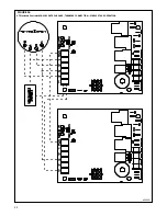
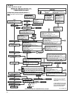
UT ELECTRONIC CONTROLS
1028-928 CONTROL BOARD
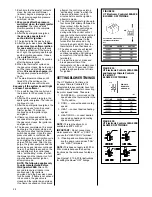
1. Single Stage Operation
(See Figure 16)
a. Control board "ONE" is on
furnace connected to the
thermostat.
b. The 24 VAC supply to both
control boards must be in phase
with each other.
c. Connect the "C," "W" and
"TWIN" terminals to
counterparts on each control.
d. Both control boards must have
switch #3 in the "ON" position.
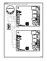
2. Two Stage Operation
(See Figure 17)
a. Follow above instructions.
Connect "W2" on thermostat to
"W" on control board "TWO".
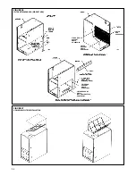
FIGURE 15
LINE VOLTAGE CONNECTIONS
UT ELECTRONIC CONTROLS 1028-928 CONTROL BOARDS
UT ELECTRONIC CONTROLS 1012-925 CONTROL BOARD
I677
INVENSYS CLIMATE CONTROLS ICC-H1MC7