


35
important that the airflow is not reduced
to maximize system performance and
life. Always verify that the systems
airflow is not impaired by the filtering
system that has been installed, by
performing a temperature rise and
temperature drop test.
Keep the air filters clean at all times.
Vacuum dirt from filter, wash with
detergent and water, air dry thoroughly
and reinstall.
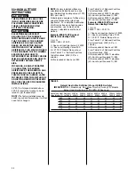
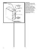
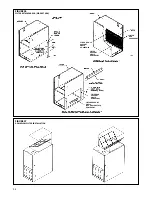
See Table 8 and Figures 24, 25, 26, and
27 for proper filter sizes and locations.
1. 14”- 50,000 BTUH unit requires
removal of 3
1
/
2
” segment of filter and
frame to get proper width for a bottom
filter.
2. 21”-100,000 BTUH unit requires
removal of 3
1
/
2
” segment of filter and
frame to get proper width for a side
filter.
3. 24
1
/
2
”-125,000 and 150,000 BTUH
units require removal of 7” segment of
filter and frame to get proper width for
a side filter.
IMPORTANT:
Do not operate the
system without filters. A portion of the
dust entrained in the air may temporarily
lodge in the air duct runs and at the
supply registers. Any recirculated dust
particles will be heated and charred by
contact with the furnace heat
exchanger. This residue will soil
ceilings, walls, drapes, carpets, and
other household articles.
SYSTEM OPERATION
INFORMATION
Advise The Customer To:
1. Keep the air filters clean. The heating
system will operate better, more
efficiently and more economically.
2. Arrange the furniture and drapes so
that the supply air registers and the
return air grilles are unobstructed.
3. Close doors and windows. This will
reduce the heating load on the
system.
4. Avoid excessive use of kitchen &
bathroom exhaust fans.
5. Do not permit the heat generated by
television, lamps or radios to
influence the thermostat operation.
6 Except for the mounting platform,
keep all combustible articles three
feet from the furnace and vent
system.
7.
IMPORTANT:
Replace all blower
doors and compartment covers after
servicing the furnace. Do not operate
the unit without all panels and doors
securely in place.
8. Proper operation of the system with
constant air circulation.
COMBUSTIBLE MATERIAL MUST
NOT BE PLACED ON OR AGAINST
THE FURNACE JACKET OR WITHIN
THE SPECIFIED CLEARANCES OF
THE VENT PIPE. THE AREA
AROUND THE FURNACE MUST BE
KEPT CLEAR AND FREE OF ALL
COMBUSTIBLE MATERIALS
INCLUDING GASOLINE AND OTHER
FLAMMABLE VAPORS AND
LIQUIDS. PLACEMENT OF
COMBUSTIBLE MATERIALS ON,
AGAINST OR AROUND THE
FURNACE JACKET CAN CAUSE AN
EXPLOSION OR FIRE RESULTING
IN PROPERTY DAMAGE,
PERSONAL INJURY OR DEATH.
THE FURNACE OWNER SHOULD BE
CAUTIONED THAT THE FURNACE
AREA MUST NOT BE USED AS A
BROOM CLOSET OR FOR ANY
OTHER STORAGE PURPOSES.
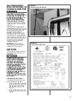
ANNUAL INSPECTION
The furnace should operate for many
years without excessive scale build-up
in the flue passageways, however, it is
recommended that a qualified installer,
service agency, or the gas supplier
actually inspect the flue passageways,
the vent system and the main and pilot
burners for continued safe operation
paying particular attention to
deterioration from corrosion or other
sources.
HOLES IN THE VENT PIPE OR HEAT
EXCHANGER CAN CAUSE TOXIC
FUMES TO ENTER THE HOME
RESULTING IN CARBON
MONOXIDE POISONING OR DEATH.
THE VENT PIPE OR HEAT
EXCHANGER MUST BE REPLACED
IF THEY LEAK.
• IMPORTANT:
It is recommended
that at the beginning of the heating
season and approximately midway
in the heating season a visual
inspection be made of the main
burner flames and pilot flame on
standing pilot models for the desired
flame appearance by a qualified
installer, service agency, or the gas
supplier.
• IMPORTANT:
It is also
recommended that at the beginning
of the heating season, the flame
sensor on hot surface ignition
models be cleaned with steel wool
by a qualified installer, service
agency, or the gas supplier.
•
IMPORTANT:
It is recommended
that an annual inspection and
cleaning of all furnace markings be
made to assure legibility. Attach a
replacement marking, which can be
obtained through the distributor, if
any are found to be illegible or
missing.
IMPORTANT: FOR Nox MODELS –
At the beginning of the heating season
a visual inspection of the Nox device
should be made to ensure they have
not become obstructed by insects
nests or anything else which may
effect performance.
REPLACEMENT PARTS
Contact your local distributor for a
complete parts list. See enclosed
sheet.
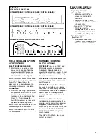
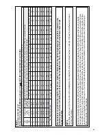
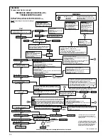
TROUBLESHOOTING
Refer to Figure 28 for determining
cause of unit problems.
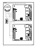
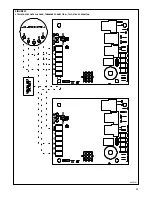
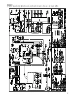
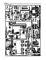
WIRING DIAGRAM
Figures 29 and 30 are complete wiring
diagrams for the furnace and power
sources.
WARNING
!
WARNING
!