Iceco 80LJ SERIES Installation Instructions Manual Download Page 13

13

GENERAL INFORMATION

The furnace must be vented in
accordance with these instructions,
National Fuel Gas Code, ANSI Z223.1
and/or the Natural Gas Installation
Code, CSA-B149.1 & .2 and
requirements or codes of the local utility
or other authority having jurisdiction.

DEVICES ATTACHED TO THE FLUE
OR VENT FOR THE PURPOSE OF
REDUCING HEAT LOSS UP THE
CHIMNEY HAVE NOT BEEN TESTED
AND HAVE NOT BEEN INCLUDED IN
THE DESIGN CERTIFICATION OF
THIS FURNACE. WE, THE
MANUFACTURER, CANNOT AND
WILL NOT BE RESPONSIBLE FOR
INJURY OR DAMAGE CAUSED BY
THE USE OF SUCH UNTESTED
AND/OR UNCERTIFIED DEVICES,
ACCESSORIES OR COMPONENTS.
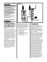
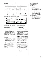
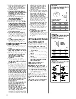
DRAFT INDUCER

VENT PIPE ATTACHING HOLES
MUST BE PREDRILLED IN THE
DRAFT INDUCER COLLAR TO
PREVENT DAMAGING THE
INDUCER. DRILL 1/8

” 

DIAMETER

HOLES THROUGH THE VENT PIPE
AND COLLAR AND USE #8 SCREWS
TO ATTACH. SEE FIGURE 9.
FAILURE TO FOLLOW THIS
WARNING CAN CAUSE
RECIRCULATION OF FLUE
PRODUCTS CAUSING CARBON
MONOXIDE POISONING
RESULTING IN PERSONAL INJURY
OR DEATH.

IMPORTANT APPLICATION
NOTES

When the furnace is used as a
replacement, the existing vent system
should be inspected to assure that
there are no obstructions, blockage, or
any signs of corrosion.

NOTE: WHEN THE VENT TABLE
PERMITS MORE THAN ONE
DIAMETER OF PIPE FOR A
CONNECTOR OR VENT, THE
SMALLEST PERMITTED DIAMETER
MUST BE USED,

VENT PIPE MAY BE TYPE “B-1,”
EITHER RIGID OR SUITABLE
FLEXIBLE CONSTRUCTION THAT
CARRIES A U.L. LISTING.

COMMON VENTING IS ALLOWED
WITH VERTICAL B-1 VENT
SYSTEMS, AND LINED MASONRY
CHIMNEYS. FOLLOW THE
NATIONAL FUEL GAS CODE, ANSI
Z223.1 AND/OR THE NATURAL GAS
INSTALLATION CODE, CSA-B149.1 &
.2 FOR PROPER INSTALLATION
PRACTICES.

SINGLE WALL VENT CONNECTORS
TO “B-1 VENT OR MASONRY
CHIMNEYS” MAY BE USED UNDER
THE GUIDELINES OF THE
NATIONAL FUEL GAS CODE, ANSI
Z223.1 AND/OR THE NATURAL GAS
INSTALLATION CODE, 
CSA-B149.1 & .2.

The entire length of the vent
connector shall be readily
accessible for inspection, cleaning
and replacement.

WARNING

!

WARNING

!

FURNACE CATEGORY
INFORMATION

This furnace is shipped as a Category 

I

type induced draft furnace. A Category

I

furnace operates with a nonpositive

vent pressure and has a vent gas
temperature at least 140°F above the
dew point of the vent gases. A
Category 

I

type may be a draft hood

equipped furnace or have a fan
assisted combustion system (induced
draft). The inducer is used to pull flue
products through the combustion
chamber and as they leave the
furnace, most of the energy has been
dissipated. The buoyant effect of the
flue gases provides venting to the
outdoors.

During the off cycle, the inducer is off
and there is very little flow through the
vent, cooling the vent. During the on
cycle there is no dilution airflow, as
with a draft hood type furnace.
Although the vent heats up rapidly
without dilution air, the flue products
contain more water vapor, which
results in a higher dew point
temperature. It is most 

important

that

you follow the guidelines in these
instructions to prevent the possible
formation of condensation in the
venting system.

As a Category 

I

furnace it may be

vented vertically with type B-1 vent
pipe and also may be common vented,
as described in these instructions.

FIGURE 9

ATTACHING TO DRAFT INDUCER COLLAR

VENTING

AO991-01

VENT PIPE

ADAPTER
CONNECTOR*

*SEE PAGE 14
VERTICAL VENTING

Summary of Contents for 80LJ SERIES

Page 1: ...CTIONS FOR UPFLOW UPFLOW HORIZONTAL AND DOWNFLOW INDUCED DRAFT GAS FURNACES 80PJ AND 80LJ SERIES PROPOSITION 65 THIS PRODUCT CONTAINS CHEMICALS INCLUDING CARBON MONOXIDE KNOWN TO THE STATE OF CALIFORN...

Page 2: ...furnace ground to electrical panel DC microamp A flame signal hot surface ignition units Correct control voltage Measure and set heat anticipator amperage Air conditioning low voltage wires connected...

Page 3: ...fects such as fiberglass insulation lead in brass and combustion products from natural gas All new equipment shipped for sale in California will have labels stating that the product contains and or pr...

Page 4: ...N PLACE SET FURNACE INPUT RATE AND TEMPERATURE RISE PER RATING PLATE MARKING MEANS FOR PROVIDING OUTDOOR AIR REQUIRED FOR COMBUSTION RETURN AIR TEMPERATURE MAINTAINED BETWEEN 55 F 13 C AND 80 F 27 C A...

Page 5: ...is unit when installed For attic or crawl space installation horizontal furnaces may be installed on combustible wood flooring or by using support brackets See Figure 1 6 IMPORTANT If installing in a...

Page 6: ...RIZONTAL MODELS TOP LEFT SIDE FRONT RIGHT SIDE BOTTOM 24 1 2 26 13 16 26 5 8 24 11 32 24 11 32 19 32 9 16 24 7 16 28 1 16 26 5 8 14 3 8 11 1 2 34 1 5 8 DIA 23 15 20 D 7 8 DIA 7 8 DIA 19 32 19 32 3 4 1...

Page 7: ...15 5 8 23 5 8 0 0 0 1 3 6 140 lbs 15 24 1 2 23 11 32 15 5 8 23 5 8 0 0 0 1 3 6 150 lbs TOP BOTTOM 24 1 2 19 3 4 C A B D LOW VOLTAGE GAS CONNECTION ELECTRIC CONNECTION E 26 5 8 26 13 16 6 3 16 20 3 8 2...

Page 8: ...uding evaporator coil if used of the entire system should not exceed 0 5 w c Be sure to have adequate space for unit filter IMPORTANT Some high efficiency filters have a greater than normal resistance...

Page 9: ...NTO THE LIVING SPACE AND CREATE POTENTIALLY HAZARDOUS CONDITIONS INCLUDING CARBON MONOXIDE POISONING OR DEATH 2 If summer air conditioning is desired position the indoor coil on the top of the unit In...

Page 10: ...unted in a closet the door must be closed when making this check of the installation DO NOT reset the overtemperature switch without taking corrective action to assure that an adequate supply of combu...

Page 11: ...ht construction contemporary construction outside air may still be required for the furnace to operate and vent properly Outside air openings should be sized the same as for a confined space FIGURE 7...

Page 12: ...uare inch for each 2000 BTUH of total input rating for all equipment in the enclosure see Figure 8 Here are typical duct sizes FIGURE 8 OUTSIDE AIR USING A HORIZONTAL INLET OUTLET B Method 2 One perma...

Page 13: ...SI Z223 1 AND OR THE NATURAL GAS INSTALLATION CODE CSA B149 1 2 FOR PROPER INSTALLATION PRACTICES SINGLE WALL VENT CONNECTORS TO B 1 VENT OR MASONRY CHIMNEYS MAY BE USED UNDER THE GUIDELINES OF THE NA...

Page 14: ...gher than any portion of a building within 10 feet 2 A type B 1 gas vent shall terminate at least 5 feet in vertical height above the highest connected equipment draft hood or flue collar 3 Must rise...

Page 15: ...operate a summer exhaust fan Close fireplace dampers 4 Follow the lighting instructions Place the appliance being inspected into operation Adjust the thermostat so the appliance will operate continuou...

Page 16: ...in size to prevent undue pressure drop and never smaller than the pipe size to the combination gas valve on the furnace Refer to Table 2 for the recom mended pipe size for natural gas and Table 3 for...

Page 17: ...ns The valve can be converted to use liquefied petroleum LP gas by replacing the pressure regulator spring with the conversion kit spring This LP kit spring allows the regulator to maintain the proper...

Page 18: ...the LP supplier adjust the line pressure at the regulator See Table 3 NOTE Depending on the amount of LP vapor and the outdoor ambient temperature the LP storage tank may require supplemental heat to...

Page 19: ...t off the manual main gas valve and remove the gas manifold 2 Replace the orifice spuds 3 Reassemble in reverse order 4 Turn the gas supply back on and check for proper operation and manifold pressure...

Page 20: ...available from the furnace manufacturer s Parts Department are acceptable Generally all thermostats that are not of the current robbing type are compatible with the integrated furnace control used NOT...

Page 21: ...with identical control boards 1 thermostat per 2 furnaces IMPORTANT Only bottom returns can be used No more than two furnaces can share the same supply and return Furnaces must have same heating and...

Page 22: ...22 I400 FIGURE 16 UT Electronic Controls 1028 928 CONTROL BOARD TWINNING CONNECTION SINGLE STAGE OPERATION a099201...

Page 23: ...23 FIGURE 17 UTEC 1028 928 CONTROL BOARD TWINNING CONNECTION TWO STAGE OPERATION a099301...

Page 24: ...lations are the best method Example 900 BTU ft3 Regional Natural Gas Heating Value I H Q 25000 900 27 78 ft 3 I Sea Level input per burner 25000 H Sea Level Heating Value 900 Q 27 78 ft 3 Natural Gas...

Page 25: ...23 000 22 000 21 000 20 000 19 000 18 000 17 000 16 000 All calculations are performed by using the first three columns of information only Before beginning any calculations determine the individual...

Page 26: ...site with manifold pressure adjustment to ensure that an actual 10 reduction in input rate is achieved Once this field adjustment has been made the label shown in Figure 18 rmust be affixed in a consp...

Page 27: ...don t light the system goes through another ignition sequence It does this up to four times 7 The main blower starts approximately 20 seconds after the burners ignite 8 When the thermostat W Heat Call...

Page 28: ...inducer run for 3 minutes before another ignition attempt is made NOTE The following applies only to units manufactured before third Quarter 2003 After a 30 second inter purge inducer runs continuous...

Page 29: ...to the furnace as possible FIGURE 21 TEMPERATURE RISE MEASUREMENT GAS FURNACE DIRECT DRIVE INSTRUCTIONS FOR CHANGING BLOWER SPEED DISCONNECT THE ELECTRICAL SUPPLY TO THE FURNACE BEFORE ATTEMPTING TO...

Page 30: ...30 BLOWER PERFORMANCE DATA 80LJ DOWNFLOW MODELS ONLY BLOWER PERFORMANCE DATA 80PJ UPFLOW HORIZONTAL MODELS...

Page 31: ...ck PRESSURE SWITCH This furnace is equipped with a normally open pressure switch that monitors pressure conditions within the furnace vent system during the heating cycle There are several reasons for...

Page 32: ...alified installer service agency or the gas supplier to prevent the possibility of overheating due to an accumulation of dust and dirt on the windings or on the motor exterior Air filters should be ke...

Page 33: ...or a filter base For systems with a return air filter grill or multiple filter grills can have a filter installed at each of the return air openings DO NOT DOUBLE FILTER THE RETURN AIR DUCT SYSTEM DO...

Page 34: ...D SIDE RETURN FIGURE 27 DOWNFLOW FILTER INSTALLATION FILTER ROD 45 24095 01 FILTER ROD SUPPORT ANGLE AE 60520 01 FILTER SUPPORT ANGLE SEE ANGLE DETAIL AE 61883 01 FILTER ROD SUPPORT ANGLE AE 60520 01...

Page 35: ...S OF THE VENT PIPE THE AREA AROUND THE FURNACE MUST BE KEPT CLEAR AND FREE OF ALL COMBUSTIBLE MATERIALS INCLUDING GASOLINE AND OTHER FLAMMABLE VAPORS AND LIQUIDS PLACEMENT OF COMBUSTIBLE MATERIALS ON...

Page 36: ...F Did a limit open during ignition trial If yes go to D Check line voltage between HEAT and NEUTRAL on IFC Check wires connections and continuity between IFC and IBM Check IBM capacitor Check IBM CHE...

Page 37: ...37 FIGURE 29 FOR MODELS WITH UT ELECTRONIC CONTROLS 1028 928 INTEGRATED FURNACE CONTROL AND DIRECT SPARK IGNITION...

Page 38: ...38 FIGURE 30 FOR MODELS WITH UT ELECTRONIC CONTROLS 1012 925 OR INVENSYS CLIMATE CONTROLS ICC H1MC7 01 INTEGRATED FURNACE CONTROL AND HOT SURFACE IGNITION...

Page 39: ...39...

Page 40: ...40 CM 0604 MANUFACTURED BY ICECO 5600 OLD GREENWOOD ROAD FORT SMITH ARKANSAS 72908...

Reviews: