


PTSN
(for Public Telephone Switched Network). The service processor
expects to use the modem on the public network, so the telephone line
should attach to the PTSN connector.
If no, continue with step 3.
3. Does your modem respond to the extended command set (prefixed with
&
)?
If yes, go to step 5.
OR
If no, continue with step 4.
4. Does your modem respond to:
v
ATZ reset command,
OR
v
ATZn reset commands, where n can be 0, 1, and so on?
If ATZ, configuration file
modem_z.cfg
is recommended. If ATZn, configuration
file
modem_z0.cfg
is recommended.
Go to step 7.
5. Does your modem command set include a test for V.42 error correction at the
remote modem (often called “Auto-Reliable Mode”)?
If yes, disable this test. You can use sample configuration files
/usr/share/modem_m0.cfg
OR
/usr/share/modem_m1.cfg
as models to help you create a file for your particular
modem. See “Customizing the Modem Configuration Files” on page 295. Go to step
7.
If no, go to step 6.
6. Does your modem respond to:
v
AT&F reset command,
OR
v
AT&Fn reset commands, where n can be 0, 1, and so on.?
If AT&F, configuration file
modem_f.cfg
is recommended.
If AT&Fn, configuration file
modem_f0.cfg
or
modem_f1.cfg
is recommended,
depending on which provides the hardware flow control profile.
7. You have completed selection of the configuration file.
If your modem configuration selection is not available in the Service Processor
Modem Configuration Menu, you must access it through the Configure Remote
Maintenance Policy Service Aid.
If you find it necessary to adjust any of these configuration files, use the manual
provided with your modem. It is recommended you select settings that enable
hardware flow control and respond to DTR.
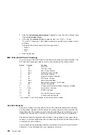
Note:
Some older modems do not respond to the commands
X0
or
&R1
. You
should edit out these commands from the modem configuration file if yours is
such a modem. See your modem manual for more information.
294
Service Guide
Summary of Contents for RS/6000 44P Series 270
Page 1: ...RS 6000 44P Series Model 270 Service Guide SA38 0572 02 ...
Page 10: ...x Service Guide ...
Page 14: ...xiv Service Guide ...
Page 16: ...xvi Service Guide ...
Page 20: ...Rear View 1 2 3 4 5 6 7 8 9 11 12 13 14 15 16 10 17 18 19 2 Service Guide ...
Page 44: ...26 Service Guide ...
Page 164: ...146 Service Guide ...
Page 204: ...186 Service Guide ...
Page 247: ...b Slide the covers to the rear and remove Chapter 9 Removal and Replacement Procedures 229 ...
Page 288: ...270 Service Guide ...
Page 290: ...1 2 3 4 5 6 7 8 9 10 11 12 13 14 15 16 17 18 19 21 20 22 23 24 25 272 Service Guide ...
Page 294: ...Keyboards and Mouse 276 Service Guide ...
Page 296: ...Keyboards and Mouse Black 278 Service Guide ...
Page 298: ...Power Cables 1 2 3 4 5 6 7 8 9 10 11 280 Service Guide ...
Page 300: ...282 Service Guide ...
Page 302: ...284 Service Guide ...
Page 304: ...286 Service Guide ...
Page 310: ...292 Service Guide ...
Page 338: ...320 Service Guide ...
Page 345: ......
Page 346: ... Printed in U S A September 2001 SA38 0572 02 ...