


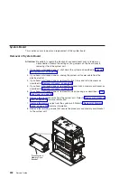


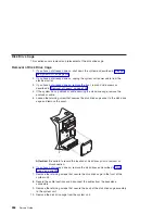
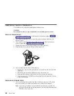


10. Remove the retaining screws that secure the power supply to the top of the
system unit.
Attention:
When you remove the power supply, ensure that the power supply
does not drop down and damage the I/O board components or
connectors.
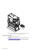
11. Slide the power supply slightly toward the front of the system unit to disengage the
power supply retainer from the top and right side of the system frame.
12. Carefully remove the power supply from the system unit.
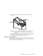
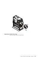
Replacement of Power Supply
To replace the power supply, perform the removal steps in the reverse order. Ensure
that the power supply retainer engages with the top and right side of the system frame,
to help align the power supply screws correctly.
Screws
Power
Supply
Chapter 9. Removal and Replacement Procedures
259
Summary of Contents for RS/6000 44P Series 270
Page 1: ...RS 6000 44P Series Model 270 Service Guide SA38 0572 02 ...
Page 10: ...x Service Guide ...
Page 14: ...xiv Service Guide ...
Page 16: ...xvi Service Guide ...
Page 20: ...Rear View 1 2 3 4 5 6 7 8 9 11 12 13 14 15 16 10 17 18 19 2 Service Guide ...
Page 44: ...26 Service Guide ...
Page 164: ...146 Service Guide ...
Page 204: ...186 Service Guide ...
Page 247: ...b Slide the covers to the rear and remove Chapter 9 Removal and Replacement Procedures 229 ...
Page 288: ...270 Service Guide ...
Page 290: ...1 2 3 4 5 6 7 8 9 10 11 12 13 14 15 16 17 18 19 21 20 22 23 24 25 272 Service Guide ...
Page 294: ...Keyboards and Mouse 276 Service Guide ...
Page 296: ...Keyboards and Mouse Black 278 Service Guide ...
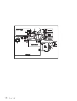
Page 298: ...Power Cables 1 2 3 4 5 6 7 8 9 10 11 280 Service Guide ...
Page 300: ...282 Service Guide ...
Page 302: ...284 Service Guide ...
Page 304: ...286 Service Guide ...
Page 310: ...292 Service Guide ...
Page 338: ...320 Service Guide ...
Page 345: ......
Page 346: ... Printed in U S A September 2001 SA38 0572 02 ...