


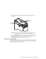
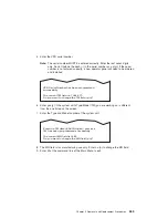


a. When installing the 6156 8 mm tape drive, remove the EMC (electro magnetic
compatibility) clip from the front position (1), to allow proper 20 GB 8 mm tape
drive operation.
b. Pull the tab that is located on the left side out slightly to remove the EMC clip.
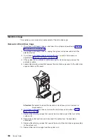
2. Align the drive with the guides at the edge of the bay.
3. Slide the drive into the system unit until it stops.
4. The diskette drive requires a 16-bit to 8-bit adapter to be installed between the
connector at the rear of the drive and the data cable. Install this adapter at this time.
5. If you are installing a disk drive, locate the media tray that you removed.
6. Secure the disk drive to the media tray with the retaining screws.
7. Connect the cables from the front of the system.
a. Locate the appropriate data cable for the drive. Connect the cable to the
connector at the rear of the drive.
b. If you are installing a CD-ROM drive, connect the audio cable from the I/O
board to the audio connector at the rear of the drive.
c. If you are installing a SCSI drive, set the SCSI address jumpers at the rear of
the drive to the correct address. Refer to the documentation provided with your
drive for details on setting the SCSI address.
d. The two media bays share a common power cable. Connect an available
connector on the power cable to the 4-pin connector at the rear of the drive.
8. Secure the media drive to the system unit with the retaining screws.
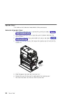
9. Replace the system unit covers as described in “Replacement of Covers” on
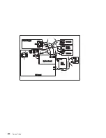
1
2
Chapter 9. Removal and Replacement Procedures
269
Summary of Contents for RS/6000 44P Series 270
Page 1: ...RS 6000 44P Series Model 270 Service Guide SA38 0572 02 ...
Page 10: ...x Service Guide ...
Page 14: ...xiv Service Guide ...
Page 16: ...xvi Service Guide ...
Page 20: ...Rear View 1 2 3 4 5 6 7 8 9 11 12 13 14 15 16 10 17 18 19 2 Service Guide ...
Page 44: ...26 Service Guide ...
Page 164: ...146 Service Guide ...
Page 204: ...186 Service Guide ...
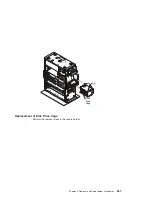
Page 247: ...b Slide the covers to the rear and remove Chapter 9 Removal and Replacement Procedures 229 ...
Page 288: ...270 Service Guide ...
Page 290: ...1 2 3 4 5 6 7 8 9 10 11 12 13 14 15 16 17 18 19 21 20 22 23 24 25 272 Service Guide ...
Page 294: ...Keyboards and Mouse 276 Service Guide ...
Page 296: ...Keyboards and Mouse Black 278 Service Guide ...
Page 298: ...Power Cables 1 2 3 4 5 6 7 8 9 10 11 280 Service Guide ...
Page 300: ...282 Service Guide ...
Page 302: ...284 Service Guide ...
Page 304: ...286 Service Guide ...
Page 310: ...292 Service Guide ...
Page 338: ...320 Service Guide ...
Page 345: ......
Page 346: ... Printed in U S A September 2001 SA38 0572 02 ...