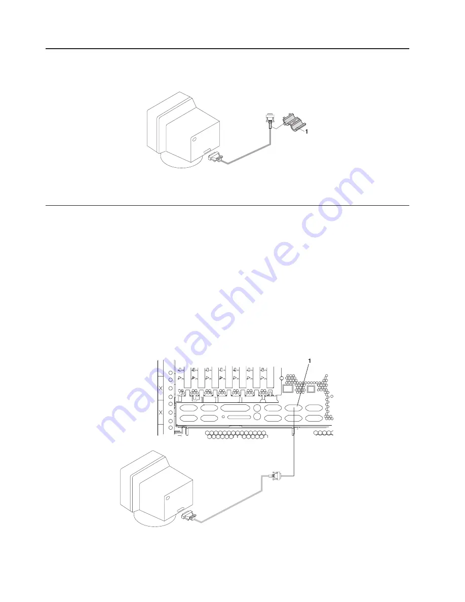
Step
9.
Attach
the
Display
Cable
Toroid
If
the
cable
for
your
display
came
with
a
separate
toroid,
install
the
toroid
using
the
installation
instructions
included
with
the
toroid.
1
Display
Cable
Toroid
Step
10.
Connect
the
Graphics
Display
Note:
If
you
have
an
ASCII
terminal,
you
must
connect
it
to
the
serial
connector
S1
(item
1
in
the
following
illustration).
If
you
are
using
an
ASCII
terminal
as
the
console
for
this
system,
and
do
not
have
a
graphics
display
to
connect,
continue
with
“Step
12.
Connect
the
Serial
and
Parallel
Devices”
on
page
20.
Connect
the
graphics
display
cable
to
the
back
of
the
display
and
to
the
graphics
adapter
connector.
For
the
locations
of
installed
adapters,
consult
the
″
About
Your
Machine
″
document.
For
more
information
about
your
display,
refer
to
the
documentation
included
with
the
display.
Notes:
1.
The
PCI
graphics
adapter
might
be
installed
in
any
of
the
PCI
slots
on
the
system
unit.
2.
Some
displays
require
an
additional
cable.
1
Serial
Connector
S1
18
Eserver
pSeries
650
Installation
Guide
Summary of Contents for pSeries 650
Page 1: ...pSeries 650 Installation Guide SA38 0610 03 ERserver...
Page 2: ......
Page 3: ...pSeries 650 Installation Guide SA38 0610 03 ERserver...
Page 8: ...vi Eserver pSeries 650 Installation Guide...
Page 12: ...x Eserver pSeries 650 Installation Guide...
Page 14: ...xii Eserver pSeries 650 Installation Guide...
Page 22: ...6 Eserver pSeries 650 Installation Guide...
Page 138: ...122 Eserver pSeries 650 Installation Guide...
Page 142: ...126 Eserver pSeries 650 Installation Guide...
Page 150: ...134 Eserver pSeries 650 Installation Guide...
Page 152: ...136 Eserver pSeries 650 Installation Guide...
Page 164: ...148 Eserver pSeries 650 Installation Guide...
Page 170: ...154 Eserver pSeries 650 Installation Guide...
Page 182: ...166 Eserver pSeries 650 Installation Guide...
Page 186: ...170 Eserver pSeries 650 Installation Guide...
Page 189: ......
Page 190: ...Part Number 80P3834 Printed in USA November 2003 SA38 0610 03 1P P N 80P3834...


