System-board layouts
The following illustrations show the connectors, LEDs, switches, and jumpers on the
system board. The illustrations in this document might differ slightly from your
hardware.
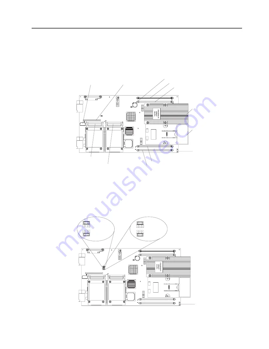
System-board connectors
The following illustration shows the connectors on the system board.
DIMM 1 (J31)
DIMM 3 (J4)
DIMM 2 (J30)
DIMM 4 (J2)
Microprocessor 1
and heat sink
Microprocessor
socket 2 and
heat sink filler
Battery (BH1)
Control panel
connector
SCSI connector 1
(J12)
SCSI connector 0
(J11)
I/O expansion option
connector (J13)
I/O expansion option
connector (J10)
System-board jumpers
The following illustration shows the jumpers on the system board.
Note:
This server does not have a power-on password override jumper. See “Using
passwords” on page 87 for information about bypassing a power-on password.
4
4
2
2
3
3
1
1
Normal
operation
Start from
backup
BIOS image
4
4
2
2
3
3
1
1
Normal
operation
Disable WOL
BIOS backup page (J16)
WOL bypass (J15)
Chapter 1. Introduction
7
Summary of Contents for LS20 - BladeCenter - 8850
Page 1: ...AMD Opteron LS20 Type 8850 for IBM BladeCenter Problem Determination and Service Guide...
Page 2: ......
Page 3: ...AMD Opteron LS20 Type 8850 for IBM BladeCenter Problem Determination and Service Guide...
Page 14: ...xii AMD Opteron LS20 Type 8850 for IBM BladeCenter Problem Determination and Service Guide...
Page 72: ...58 AMD Opteron LS20 Type 8850 for IBM BladeCenter Problem Determination and Service Guide...
Page 104: ...90 AMD Opteron LS20 Type 8850 for IBM BladeCenter Problem Determination and Service Guide...
Page 114: ...100 AMD Opteron LS20 Type 8850 for IBM BladeCenter Problem Determination and Service Guide...
Page 115: ......
Page 116: ...Part Number 49Y0167 Printed in USA 1P P N 49Y0167...


