


Chapter 6. Installing options
53
System board switch block
The switch block contains microswitches 1 through 4. Switch 1 is at the top of the
switch block and switch 4 is at the bottom. For more information about this switch
block see “Power-on password” on page 26.
The following table describes the function for each switch.
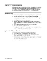
System board LEDs
The following illustration identifies the LEDs on the system board.
Figure 11. Viewing the system board connectors
Table 5. Switches 1 through 4.
Switch
number
Switch
description
1
Reserved. The default setting is Off (disabled).
2
Reserved. The default setting is Off.
3
Reserved. The default setting is Off.
4
Bypass power-on password.
When this switch is toggled to the opposite position, the system bypasses
the power on password, if one is set. See “Power-on password” on page
26.
Light Path
Diagnostic circuit
verification LED
Light Path
Diagnostics
button
Light Path
Diagnostics
panel
Fan 1
failure
(CR15)
Fan 3
failure (CR31)
Fan 5
failure (CR40)
Fan 4
failure (CR33)
Fan 6
failure (CR48)
Fan 2
failure
(CR17)
Microprocessor 1
failure (CR26)
Microprocessor 2
failure (CR53)
DIMM 4
failure
(CR 54)
DIMM 3
failure
(CR 46)
DIMM 2
failure
(CR 39)
DIMM 1
failure
(CR 38)
Power-on
indicator
(CR47)
PS
TEMP
FA
N
SP
MEM
CPU
VRM
PCI
Light
P
ath
Remote supervisor
adapter connector
Summary of Contents for eServer 130 xSeries
Page 1: ...User s Reference xSeries 130 ...
Page 2: ......
Page 3: ...IBM IBM xSeries 130 User s Reference ...
Page 8: ...vi IBM xSeries 130 User s Reference ...
Page 14: ...xii IBM xSeries 130 User s Reference ...
Page 46: ...32 IBM xSeries 130 User s Reference ...
Page 58: ...44 IBM xSeries 130 User s Reference ...
Page 62: ...48 IBM xSeries 130 User s Reference ...
Page 96: ...82 IBM xSeries 130 User s Reference ...
Page 136: ...122 IBM xSeries 130 User s Reference ...
Page 154: ...140 IBM xSeries 130 User s Reference ...
Page 155: ......
Page 156: ...IBM Part Number 32P0093 Printed in U S A 32P 93 ...


