background image

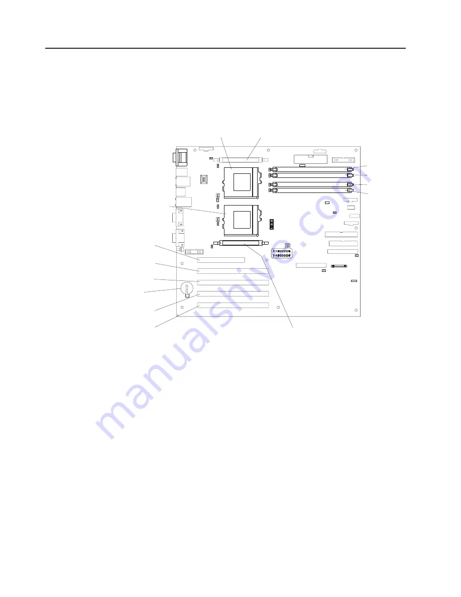
System board layout

The illustrations in the following sections show the components on the system
board.

System board options connectors

The following illustration shows a layout of the system board and identifies
system-board connectors for user-installable options.

DIMM 4 (J4)

DIMM 3 (J3)

DIMM 2 (J2)

DIMM 1 (J1)

PCI Slot 1
32-bit (J44)

PCI Slot 2
64-bit (J41)

PCI Slot 3
64-bit (J42)

PCI Slot 4
64-bit (J29)

PCI Slot 5
64-bit (J30)

Battery
(BH1)

Microprocessor 1
(U68)

Microprocessor 2
(U69)

VRM 1 connector (J37)

VRM 2 connector (J38)

34

Hardware Maintenance Manual: xSeries 342 Type 8669

Summary of Contents for 8669 - Eserver xSeries 342

Page 1: ...Hardware Maintenance Manual xSeries 342 Type 8669 ERserver...

Page 2: ......

Page 3: ...Hardware Maintenance Manual xSeries 342 Type 8669 ERserver...

Page 4: ...ypographical errors Changes are periodically made to the information herein these changes will be incorporated in new editions of the publication IBM may make improvements and or changes in the produc...

Page 5: ...Important safety information Be sure to read all caution and danger statements in this book before performing any of the instructions See Safety information on page 109 Leia todas as instru es de cui...

Page 6: ...a atentamente todas las declaraciones de precauci n y peligro ante de llevar a cabo cualquier operaci n Online support Use the World Wide Web WWW to download Diagnostic BIOS Flash and Device Driver fi...

Page 7: ...essages 13 Text messages 14 Starting the diagnostic programs 15 Viewing the test log 16 Diagnostic error message tables 16 Recovering BIOS code 16 Troubleshooting the Ethernet controller 17 Network co...

Page 8: ...llation 53 Microprocessor installation in Models 1RX 2RX 4RX 1TG 2TG 4TG 54 Microprocessor installation in Model 5RX 56 Hot swap power supply installation 61 3 Pack Ultra 160 Hot Swap Expansion Kit 63...

Page 9: ...ated system shutdown 101 Temperature related system shutdown 101 DASD checkout 101 Host Built In Self Test BIST 102 Bus fault messages 102 Undetermined problems 102 Parts listing xSeries 342 105 Syste...

Page 10: ...viii Hardware Maintenance Manual xSeries 342 Type 8669...

Page 11: ...g system is not part of a shared DASD cluster A system might be part of a cluster if v The customer identifies the system as part of a cluster v One or more external storage units are attached to the...

Page 12: ...Error LED if on see Information panel system error LED on page 85 v Check the System Error Log If an error was recorded by the system see Symptom to FRU index on page 83 v Start the Diagnostic Progra...

Page 13: ...following World Wide Web address http www ibm com eserver xseries Features and specifications The following table provides a summary of the features and specifications for the xSeries 342 Microprocess...

Page 14: ...ting 53 dBa maximum Environment v Air temperature Server on 10 to 35 C 50 to 95 F Altitude 0 to 914 m 2998 ft Server on 10 to 32 C 50 to 89 6 F Altitude 914 m 2998 ft to 2133 m 6998 ft Server off 10 t...

Page 15: ...on the system board is lit when the power load is 270 watts or greater with two power supplies installed v Large system memory The memory bus in the server supports up to 4 GB GB equals approximately...

Page 16: ...ilable when you want to use it and that should a failure occur you can easily diagnose and repair the failure with minimal inconvenience The following is an abbreviated list of the RAS features that t...

Page 17: ...ver you must unplug the server power cords from the electrical outlets or from the UPS Power control button shield You can install this circular disk over the power control button to prevent accidenta...

Page 18: ...ply During normal operation both the AC and DC Power lights are on For any other combination of lights see Power supply LED errors on page 92 Operator information panel SCSI Hard Drive Activity Light...

Page 19: ...e server is off and the wake up feature is enabled in the Configuration Setup utility program the wake up feature will turn on the server at the set time v The Integrated System Management Processor c...

Page 20: ...off all power to the server Note Wait about 15 seconds after disconnecting the power cords for the system to stop running Watch for the System Power light on the operator information panel to stop bli...

Page 21: ...that occurred See Light path diagnostics for more information Identifying problems using LEDs The server has LEDs to help you identify problems with some server components These LEDs are part of the...

Page 22: ...n error message appears on the screen See Beep symptoms on page 83 and POST error messages for more information Notes 1 If you have a power on password or administrator password set with Remote Superv...

Page 23: ...models If you receive a SCSI error message while using the SCSISelect Utility use the following list to determine the possible cause of the error and what action to take Note If the server does not h...

Page 24: ...the exact test failure that was encountered iii is the three digit device ID date is the date that the diagnostic test was run and the error recorded cc is the check digit that is used to verify the v...

Page 25: ...m the list that appears then follow the instructions on the screen Notes a If the server stops during testing and you cannot continue restart the server and try running the diagnostic programs again b...

Page 26: ...re that the server has the latest levels of BIOS Integrated System Management Processor ServeRAID and diagnostics microcode installed Recovering BIOS code If the BIOS code has become damaged such as f...

Page 27: ...ble If you set the Ethernet controller to operate at 100 Mbps you must use Category 5 cabling If you directly connect two workstations without a hub or if you are not using a hub with X ports use a cr...

Page 28: ...the most recent device driver available from the World Wide Web v Run the network diagnostic program If the problem remains go to Starting the diagnostic programs on page 15 to run the diagnostic pro...

Page 29: ...ower distribution busses Usually a short circuit will cause the power subsystem to shut down because of an overcurrent condition A general procedure for troubleshooting power problems is as follows 1...

Page 30: ...battery To replace the battery 1 Review the information in Before you begin on page 40 and any special handling and installation instructions supplied with the replacement battery 2 Turn off the serv...

Page 31: ...er and connect the cables 6 Turn the server on 7 Start the Configuration Setup Utility program and set configuration parameters v Set the system date and time v Set the power on password v Reconfigure...

Page 32: ...22 Hardware Maintenance Manual xSeries 342 Type 8669...

Page 33: ...ou can use these CDs during the initial installation of the server to configure the server hardware and simplify the network operating system installation The ServerGuide CDs also contain a collection...

Page 34: ...f memory installed Changes that you make to configuration settings appear on this summary screen You cannot edit the fields v Product Data Select this choice to view system information such as the mac...

Page 35: ...Alert on LAN BIOS You can enable Alert on LAN support with this option The default setting for this menu item is Disabled v Advanced Setup Select this choice to change values for advanced hardware fea...

Page 36: ...delete your changes and restore the previous settings v Load Default Settings Select this choice to cancel your changes and restore the factory settings v Exit Setup If you have made any changes the...

Page 37: ...d in Setting the password override switch v Remove the battery and then install the battery Setting the password override switch The following illustration shows the location of the password override...

Page 38: ...art the SCSISelect utility program 1 Turn on the server 2 When the Press CTRL A for SCSISelect Utility prompt appears press Ctrl A 3 When prompted select either channel A or channel B 4 Use the arrow...

Page 39: ...the selected drives are ready an Unexpected SCSI Command Failure screen might appear Restart the server and watch the SCSISelect messages as each drive spins up After the drive that you want to view...

Page 40: ...s product To change the boot order use the Configuration Setup utility See Using the Configuration Setup Utility program on page 23 for more information v Show setup prompt Select this choice to eithe...

Page 41: ...en using a non ACPI operating system do not send a wake up packet to the server while it is turned on If a wake up packet has been sent while the server is on you must turn off the server Configuratio...

Page 42: ...32 Hardware Maintenance Manual xSeries 342 Type 8669...

Page 43: ...s function For complete information about installing or removing a hot swap or hot plug component see the information provided in the detailed procedures in this document under Hot swap drive installa...

Page 44: ...the system board and identifies system board connectors for user installable options DIMM 4 J4 DIMM 3 J3 DIMM 2 J2 DIMM 1 J1 PCI Slot 1 32 bit J44 PCI Slot 2 64 bit J41 PCI Slot 3 64 bit J42 PCI Slot...

Page 45: ...or J25 Fan 2 J48 DASD I2C connector J9 Fan 3 J26 Fan 1 J28 Operator information panel J39 IDE J40 Power backplane signal connector J43 Diskette J18 Flash boot block recovery jumper J16 Main power conn...

Page 46: ...nd jumpers The following illustrations identify the switches and jumpers on the system board Password override switch switch 6 of switch block 1 8 7 6 5 4 3 2 1 SW1 Serial ports J20 Mouse keyboard por...

Page 47: ...block jumper System board switch block The switch block contains microswitches 1 8 As shown in this illustration switch 8 is at the top of the switch block and switch 1 is at the bottom The following...

Page 48: ...hange them System board LED locations The following illustration identifies LEDs on the system board You might need to refer to this figure when solving problems with the server DIMM 4 error LED CR15...

Page 49: ...near the appropriate VRM is turned on by the integrated system management processor DASD System board or SCSI hot swap hard disk drive failure hard disk drive removed from either standard or optional...

Page 50: ...then an error has occurred See SP LED at Information panel system error LED on page 85 Before you begin Before you begin to install options in the server read the following information v Become famil...

Page 51: ...ormation on temperature error messages see Temperature error messages on page 99 Working inside a server with power on The server supports hot plug hot add and hot swap devices and it is designed to o...

Page 52: ...tic protective package that the option comes in on a smooth level surface and place the option on it v Do not place the option on the server s covers or any metal surface Locations The following secti...

Page 53: ...le when installing moving or opening covers on this product or attached devices To connect a Turn everything OFF b First attach all cables to devices c Attach signal cables to connectors d Attach powe...

Page 54: ...tomatically disables the integrated video controller The following illustration shows the location of the PCI expansion slots on the system board PCI Slot 1 32 bit 33 MHz J44 System management connect...

Page 55: ...C The system scans PCI slot 1 the system board Ethernet PCI slots 2 5 the system board SCSI channel A and the system board SCSI channel B if you have not changed the boot precedence from the default...

Page 56: ...re use Attention Expansion slot covers must be installed on the openings for all vacant slots This maintains the electromagnetic emissions characteristics of the system and ensures proper cooling of s...

Page 57: ...e more data Several types of drives are available such as v Diskette v Hard disk v CD ROM v Tape The server contains hardware that lets you replace a failed hard disk drive without turning off the ser...

Page 58: ...esign called small computer system interface or SCSI This design allows you to attach multiple drives to a single SCSI channel Notes 1 Any information about SCSI drives also applies to other SCSI devi...

Page 59: ...ve to turn off the server to install hot swap drives However you must turn off the server when performing any steps that involve installing or removing cables Drive tray assembly Drive handle Filler p...

Page 60: ...ve a drive installed in the bay Note The electromagnetic interference EMI integrity and cooling are protected by having the non hot swap bays covered or occupied When you install a drive save the fill...

Page 61: ...stall or remove do so now otherwise go to Installing the server cover and bezel on page 64 Memory modules Adding memory to the server is an easy way to make programs run faster You can increase the am...

Page 62: ...disconnect all external cables and power cords 3 Remove the cover See Removing the cover and bezel on page 42 4 Touch the static protective package containing the DIMM to any unpainted metal surface...

Page 63: ...ve do so now otherwise go to Installing the server cover and bezel on page 64 Microprocessor installation The server comes with one microprocessor installed on the system board If you install an addit...

Page 64: ...tical Microprocessor installation in Models 1RX 2RX 4RX 1TG 2TG 4TG To install an additional microprocessor in Models 1RX 2RX 4RX 1TG 2TG 4TG 1 Review the information in Before you begin on page 40 2...

Page 65: ...carefully press the microprocessor into the connector Make sure that the corner with the gold arrow is lined up with pin C1 on the planar c Press down and latch the release arm Note To remove a microp...

Page 66: ...nector on the system board J46 Make sure the cable is not in a position to interfere with the fan sink operation 14 Reinstall the air baffle Make sure the sides of the air baffle fit inside the bracke...

Page 67: ...from your hardware Fan 3 assembly Air baffle assembly 4 Lift and remove the air baffle assembly from the server 5 Install the microprocessor a Pull out and lift up the release lever then remove the t...

Page 68: ...d latch the release lever 6 Install the voltage regulator module VRM included in the microprocessor kit Attention When installing or replacing a VRM you must use the same type of VRM that comes shippe...

Page 69: ...retention clip on the rear of the heat sink onto the tab located on the rear of the microprocessor connector the side facing the rear of the server d Press down and latch the spring retention clip loc...

Page 70: ...that comes installed in your server to ensure proper server operation Attention Once the air baffle has been modified for use with two microprocessors it will no longer function adequately for use wit...

Page 71: ...r to the server to install a hot swap power supply v Statement 8 CAUTION Never remove the cover on a power supply or any part that has the following label attached Hazardous voltage current and energy...

Page 72: ...ing 3 Install the power supply in the bay a Place the handle on the power supply in the open position pinch the side clips and slide the power supply into the chassis b Gently close the handle to seat...

Page 73: ...s to remove the filler panels from the bays below the CD ROM drive 4 Refer to the documentation provided with the option to assemble the hot swap expansion option 5 Slide the hot swap expansion option...

Page 74: ...of the fan assembly and and pulling the fan assembly away from the server 3 Slide the replacement fan assembly into the server until it clicks into place 4 Verify that the FAN LED on the diagnostics p...

Page 75: ...s properly Setting SCSI IDs for external devices Each SCSI device that is connected to a SCSI controller must have a unique SCSI ID so that the SCSI controller can identify the devices and ensure that...

Page 76: ...ll automatically disable the integrated video adapter The following table shows the pin number assignments for the 15 pin analog video connector on the rear of the server 1 5 11 15 Pin Signal Pin Sign...

Page 77: ...connected 3 Ground 4 5 V dc 5 Clock 6 Not connected Ultra 160 SCSI ports The server has an integrated dual channel Ultra 160 small computer system interface SCSI controller This controller supports tw...

Page 78: ...ting SCSI IDs Each SCSI device connected to a SCSI controller must have a unique SCSI ID This ID enables the SCSI controller to identify the device and ensure that different devices on the same SCSI c...

Page 79: ...ic ports and some modems function properly only at certain communication port addresses You might need to use the Configuration Setup Utility program to change communication port address assignments t...

Page 80: ...t the USB keyboard emulates a mouse and you will not be able to disable the mouse settings in the Configuration Setup Utility program USB cables and hubs You need a 4 pin cable to connect devices to U...

Page 81: ...nect it to the same logical segment as the primary Ethernet controller you can configure the server to support a failover function You can configure either the integrated Ethernet controller or the NI...

Page 82: ...the following software in the order listed 1 IBM Failover DMI Agent 2 IBM PCI Hot Plug Solution 3 IBM Netfinity 10 100 Fault Tolerant Adapter device drivers Note The order of installation is importan...

Page 83: ...is located at PCI bus A slot 2 Two options are available for recovering from a failover condition The options are determined by the Enable for DMI Hot Swap Support checkbox If the IBM Netfinity Hot P...

Page 84: ...te of the failover function and the location of the redundant pair You can use the NetWare Monitor to view the custom counters Note If the primary adapter was hot replaced while the Ethernet traffic w...

Page 85: ...the server The following illustration shows input output connectors and cable routing for the server Note The illustrations in this document might differ slightly from your hardware Mouse Serial B Ser...

Page 86: ...76 Hardware Maintenance Manual xSeries 342 Type 8669...

Page 87: ...tion on page 109 Before you begin on page 40 and Handling static sensitive devices on page 41 To remove the LED cover do the following 1 Turn off server and disconnect all external cables and power co...

Page 88: ...on page 40 and Handling static sensitive devices on page 41 To remove the on off reset board 1 Turn off server and disconnect all external cables and power cords 2 Remove the cover See Removing the co...

Page 89: ...itive devices on page 41 To remove the hot swap hard disk drive backplane 1 Turn off server and disconnect all external cables and power cords 2 Remove the cover See Removing the cover and bezel on pa...

Page 90: ...our screws 3 8 Gently lift up to remove the backplane board Power supply backplane Note Before beginning read Safety information on page 109 and Handling static sensitive devices on page 41 To remove...

Page 91: ...cover See Removing the cover and bezel on page 42 3 Remove screw 1 4 Pull the AC distribution box 1 toward front of machine in order to release it from the chassis clips 3 5 Remove the two hot swap p...

Page 92: ...re that the customer provides on a diskette or CD image 1 Turn off server and disconnect all external cables and power cords 2 Remove the cover See Removing the cover and bezel on page 42 3 Remove the...

Page 93: ...s Description 1 2 3 v One beep v A pause or break v Two beeps v A pause or break v Three Beeps 4 Four continuous beeps Beep Symptom FRU Action 1 1 3 CMOS write read test failed 1 Battery 2 System Boar...

Page 94: ...1 Battery 2 System Board 3 2 1 Serial port failed 1 System Board 3 2 2 Parallel port failed 1 System Board 3 2 4 Failure comparing CMOS memory size against actual 1 DIMM 2 Battery 3 3 1 Memory size mi...

Page 95: ...Options Power On Status to enable 2 Check speaker connection 3 System Board No ac power Power supply ac LED is off 1 Check the power cord 2 Power Supply If two are installed swap them to determine if...

Page 96: ...PCI C LED on 1 Card in slots 4 5 2 Remove all PCI adapters from slots 1 5 3 System Board VRM LED on The LED next to the failing VRM should be on 1 Voltage regulator module indicated by the VRM LED on...

Page 97: ...ecommended temperature 4 If the CPU LED on the diagnostics panel is also on one of the microprocessors has caused the error FAN LED on 1 Check individual fan LEDs 2 Replace respective fan 3 Fan Cable...

Page 98: ...h test 1 PCI Hot Swap Latch Assembly 2 System Board 020 XXX 004 Failed Hot Swap Slot 4 PCI Latch test 1 PCI Hot Swap Latch Assembly 2 System Board 030 XXX 000 Failed Internal SCSI interface test 1 Sys...

Page 99: ...ntial FRUs power backplane system board 1 Reseat cables between Power Backplane and planar 2 Power Backplane 3 System board 166 201 004 System Management Failed I2C Bus Error s ISMP indicates I2C erro...

Page 100: ...DIMM 1 2 DIMM 2 3 DIMM 3 4 DIMM 4 2 System Board 201 XXX 999 Multiple DIMM failure see error text 1 See error text for failing DIMMs 2 System Board 202 XXX 001 Failed System Cache test 1 VRM 1 2 Micro...

Page 101: ...rs on multiple tape drives see error text for more info 1 See error messages text in the PC Doctor error log for detailed information on each individual tape drive error 301 XXX 000 Failed Keyboard te...

Page 102: ...efer to the information that comes with the monitor for adjusting and testing instructions 1 Monitor 2 Run Video Diagnostics If diagnostics pass the problem may be a video driver 3 Display Adapter Sys...

Page 103: ...ntil you isolate the problem 3 Power Supply 4 Power Backplane 5 System Board On On Power is OK N A POST error codes In the following error codes X can be any number or letter Error Code Symptom FRU Ac...

Page 104: ...Run Configuration Setup 2 System Board 186 Security hardware control logic failed 1 Run Configuration Setup 2 System Board 187 VPD serial number not set 1 Set serial number in Setup 2 System Board 18...

Page 105: ...Parallel port error 1 Disconnect external cable on parallel port 2 Run Configuration Setup 3 System Board 11XX System board serial port 1 or 2 error 1 Disconnect external cable on serial port 2 Run Co...

Page 106: ...ice Processor 1 Remote Supervisor Adapter if installed 2 System Board 1762 Fixed Disk Configuration error 1 Fixed Disk Drive 2 Fixed Disk Cables 3 Run Configuration Setup 4 Fixed Disk Adapter 5 SCSI B...

Page 107: ...all other adapters are set correctly in the Configuration Setup Utility program If the memory resource settings are not correct change the settings 3 If all memory resources are being used you might n...

Page 108: ...me stepping level and cache size 2 Processor 2 I9990301 Fixed disk sector error 1 Hard Disk Drive 2 SCSI Backplane 3 Cable 4 System Board I9990305 Fixed disk sector error no operating system installed...

Page 109: ...ning direct access storage device bay X had under temperature condition 1 Ambient temperature must be within normal operating specifications see Features and specifications on page 3 DASD Over Tempera...

Page 110: ...ower supply X Power supply X 12V fault level critical overcurrent condition detected 1 See Power checkout on page 19 Power supply X 3 3V fault level critical 3 3V power supply X had an error 1 See Pow...

Page 111: ...to CPU X over temperature level critical CPU X is over temperature 1 Ensure system is being properly cooled see System reliability considerations on page 41 2 Replace CPU X System shutoff due to CPU...

Page 112: ...Replace Power Backplane 5 Replace Power Supply 6 Replace System board Failure reading 12C device Check devices on bus 3 1 Reseat Cable Signal I2C IO Planar to SCSI Backplane between DASD backplane an...

Page 113: ...Power Backplane c System Board d 1 Microprocessor and VRM e 1 Terminator Card f Memory Module with a minimum of two 128 MB DIMMs 4 Power on the computer If the problem remains suspect the following FR...

Page 114: ...104 Hardware Maintenance Manual xSeries 342 Type 8669...

Page 115: ...rts listing xSeries 342 This parts listing supports the xSeries 342 Type 8669 Models 1RX 2RX 4RX 5RX 1TG 2TG 4TG 1 2 3 4 5 6 7 8 9 10 11 12 13 14 15 16 17 18 19 20 21 22 Copyright IBM Corp 2000 2001 1...

Page 116: ...Assembly All models 06P5931 14 Planar Models 1RX 1TG 2RX 2TG 4RX 4TG 48P9072 14 Planar Model 5RX 49P3064 15 Voltage Regulator Module 24P6893 16 Terminator Card Assembly All models 25P1866 17 133 1000...

Page 117: ...P5922 Cable Signal All models 06P5978 Cable Signal LVD SCSI Planar to SCSI Backplane All models 37L0350 Cable Power Power Backplane to IO Planar 2X12 All models 37L0354 Cable Power PWR BP to SCSI BP M...

Page 118: ...ndi Cameroon Central African Rep Chad Czech Republic Egypt Finland France French Guiana Germany Greece Guinea Hungary Iceland Indonesia Iran Ivory Coast Jordan Lebanon Luxembourg Macau Malagasy Mali M...

Page 119: ...zards to the customer or that makes the equipment unsafe v Before you start the machine ensure that other service representatives and the customer s personnel are not in a hazardous position v Place r...

Page 120: ...hanical inspection Working near power supplies Removing or installing main units v Before you start to work on the machine unplug the power cord If you cannot unplug it ask the customer to power off t...

Page 121: ...ntent of this inspection guide is to assist you in identifying potentially unsafe conditions on these products Each machine as it was designed and built had required safety items installed to protect...

Page 122: ...e charge Notes 1 Use product specific ESD procedures when they exceed the requirements noted here 2 Make sure that the ESD protective devices you use have been certified ISO 9000 as fully effective Wh...

Page 123: ...n statement appear in this section under statement 1 Be sure to read all caution and danger statements before performing any of the instructions v Statement 1 DANGER Electrical current from power tele...

Page 124: ...ode if not properly used handled or disposed of Do not v Throw or immerse into water v Heat to more than 100 C 212 F v Repair or disassemble Dispose of the battery as required by local ordinances or r...

Page 125: ...pply do not turn off the electrical current supplied to the device The device also might have more than one power cord To remove all electrical current from the device ensure that all power cords are...

Page 126: ...s v Conecte todos os equipamentos ao qual esse produto ser conectado a tomadas corretamente instaladas v Sempre que poss vel utilize apenas uma das m os para conectar ou desconectar cabos de sinal v N...

Page 127: ...iar a bateria pelo correio para a IBM Instru o 3 PRECAUCI N Quando produtos a laser unidades de CD ROM unidades de DVD dispositivos de fibra tica transmissores etc estiverem instalados observe o segui...

Page 128: ...rica fornecida ao dispositivo O dispositivo tamb m pode ter mais de um cabo de alimenta o Para remover toda a corrente el trica do dispositivo assegure que todos os cabos de alimenta o estejam descone...

Page 129: ...Related service information 119...

Page 130: ...120 Hardware Maintenance Manual xSeries 342 Type 8669...

Page 131: ...Related service information 121...

Page 132: ...122 Hardware Maintenance Manual xSeries 342 Type 8669...

Page 133: ...Related service information 123...

Page 134: ...124 Hardware Maintenance Manual xSeries 342 Type 8669...

Page 135: ...Related service information 125...

Page 136: ...126 Hardware Maintenance Manual xSeries 342 Type 8669...

Page 137: ...c bl s tout quipement connect ce produit v Lorsque cela est possible n utilisez qu une seule main pour connecter ou d connecter les c bles d interface v Ne mettez jamais un quipement sous tension en c...

Page 138: ...uits laser sont install s tels que des unit s de CD ROM ou de DVD des p riph riques contenant des fibres optiques ou des metteurs r cepteurs prenez connaissance des informations suivantes v N ouvrez p...

Page 139: ...imentation ne coupent pas l arriv e de courant lectrique l int rieur de la machine Il se peut que votre unit dispose de plusieurs cordons d alimentation Pour isoler totalement l unit du r seau lectriq...

Page 140: ...osen mit ordnungsgem geerdetem Schutzkontakt anschlie en v Signalkabel m glichst einh ndig anschlie en oder l sen v Keine Ger te einschalten wenn die Gefahr einer Besch digung durch Feuer Wasser oder...

Page 141: ...e Einheiten mit Glasfaserkabeln oder Transmitter installiert ist beachten Sie folgendes v Das Entfernen der Abdeckungen des CD ROM Laufwerks kann zu gef hrlicher Laserstrahlung f hren Es befinden sich...

Page 142: ...er am Netzteil wird die Stromversorgung f r den Server nicht unterbrochen Der Server k nnte auch mehr als ein Netzkabel aufweisen Um die gesamte Stromversorgung des Servers auszuschalten mu sichergest...

Page 143: ...are qualsiasi apparecchiatura collegata a questo prodotto ad una presa elettrica correttamente cablata e munita di terra di sicurezza v Quando possibile collegare o scollegare i cavi di segnale con un...

Page 144: ...ionali e locali Avviso 3 ATTENZIONE Quando si installano prodotti laser come ad esempio le unit DVD CD ROM a fibre ottiche o trasmettitori prestare attenzione a quanto segue v Non rimuovere i coperchi...

Page 145: ...o sull alimentatore non disattiva la corrente elettrica fornita all unit L unit potrebbe disporre di pi di un cavo di alimentazione Per disattivare la corrente elettrica dall unit accertarsi che tutti...

Page 146: ...136 Hardware Maintenance Manual xSeries 342 Type 8669...

Page 147: ...Related service information 137...

Page 148: ...138 Hardware Maintenance Manual xSeries 342 Type 8669...

Page 149: ...tomas de alimentaci n con un cableado correcto cualquier equipo que vaya a estar conectado a este producto v Si es posible utilice una sola mano cuando conecte o desconecte los cables de sent al v No...

Page 150: ...legislaci n local Declaraci n 3 PRECAUCI N Cuando instale productos l ser como por ejemplo CD ROM unidades DVD dispositivos de fibra ptica o transmisores tenga en cuenta las advertencias siguientes v...

Page 151: ...gan la corriente el ctrica suministrada al dispositivo Es posible tambi n que el dispositivo tenga m s de un cable de alimentaci n Para eliminar la corriente el ctrica del dispositivo aseg rese de des...

Page 152: ..._____________________ _________________________________________ 2 What would you like to see added changed or deleted in this manual _________________________________________ _________________________...

Page 153: ...Have the same adapters attachments in the same locations 4 Have the same address jumpers terminators cabling 5 Have the same software versions and levels 6 Have the same Reference Diagnostics Diskette...

Page 154: ...r both Active PCI Predictive Failure Analysis Alert on LAN ServeRAID Chipkill ServerGuide EtherJet ServerProven e business logo TechConnect HelpCenter Update Connector HelpWare Wakeon LAN IBM xSeries...

Page 155: ......

Page 156: ...Part Number 24P2922 1P P N 24P2922...

Reviews: