


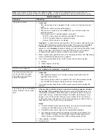


Note:
See Chapter 8, “Parts listing, Type 8482 and 8487,” on page 99 to determine which components are
replaceable by the customer (CRU), and which components must be replaced by a field service technician (FRU).
Error code/symptom
FRU/action
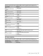
217-198-XXX
(Could not establish drive parameters)
1.
Check cable and termination.
2. Hard disk drive backplane.
3. SCSI daughter card
4. Hard disk drive.
217-XXX-00n
(Failed hard disk drive test)
Note:
If RAID is configured, the hard disk
drive number refers to the RAID logical
array.
1.
Hard disk drive n
2. SCSI card
3. Hard disk drive backplane
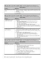
301-XXX-000
(Failed keyboard test)
v
Keyboard
v
System board
302-XXX-000
(Failed mouse test)
v
Mouse
v
System board
405-XXX-000
(Failed Ethernet test on controller on the
system board)
1.
Verify that Ethernet is not disabled in BIOS.
2. System board.
405-XXX-00n
(Failed Ethernet test on adapter in PCI slot
n)
1.
For n=0, system board
2. For n>0, adapter in PCI slot n
3. System board
405-XXX-a0n
(Failed Ethernet test on adapter in PCI slot
a)
1.
For a = 0, system board
2. For a > 0, adapter in PCI slot a
415-XXX-000
(Failed Modem test)
Note:
Error message may indicate modem
is not supported.
1.
Cable
Note:
Ensure modem is present and attached to server.
2. Modem
3. System board
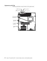
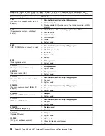
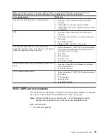
System board LEDs
Note:
See Chapter 8, “Parts listing, Type 8482 and 8487,” on page 99 to determine which components are
replaceable by the customer (CRU), and which components must be replaced by a field service technician (FRU).
LED
FRU/action
DIMM x
1.
DIMM x
2. System board
Standby power
Note:
Normal operation is
indicated when this LED is lit and
the server is connected to an ac
power source. A problem is
indicated if the LED is not lit
when connected to ac power.
1.
Power supply
2. System board
System fan 2
1.
Fan 2
2. System board
Chapter 7. Symptom-to-FRU index
85
Summary of Contents for 84875MU
Page 1: ...xSeries 206 Type 8482 and 8487 Hardware Maintenance Manual and Troubleshooting Guide...
Page 2: ......
Page 3: ...xSeries 206 Type 8482 and 8487 Hardware Maintenance Manual and Troubleshooting Guide...
Page 6: ...iv xSeries 206 Type 8482 and 8487 Hardware Maintenance Manual and Troubleshooting Guide...
Page 10: ...viii xSeries 206 Type 8482 and 8487 Hardware Maintenance Manual and Troubleshooting Guide...
Page 22: ...12 xSeries 206 Type 8482 and 8487 Hardware Maintenance Manual and Troubleshooting Guide...
Page 68: ...58 xSeries 206 Type 8482 and 8487 Hardware Maintenance Manual and Troubleshooting Guide...
Page 86: ...76 xSeries 206 Type 8482 and 8487 Hardware Maintenance Manual and Troubleshooting Guide...
Page 127: ...Appendix B Related service information 117...
Page 128: ...118 xSeries 206 Type 8482 and 8487 Hardware Maintenance Manual and Troubleshooting Guide...
Page 129: ...Appendix B Related service information 119...
Page 130: ...120 xSeries 206 Type 8482 and 8487 Hardware Maintenance Manual and Troubleshooting Guide...
Page 131: ...Appendix B Related service information 121...
Page 132: ...122 xSeries 206 Type 8482 and 8487 Hardware Maintenance Manual and Troubleshooting Guide...
Page 133: ...Appendix B Related service information 123...
Page 143: ...Appendix B Related service information 133...
Page 144: ...134 xSeries 206 Type 8482 and 8487 Hardware Maintenance Manual and Troubleshooting Guide...
Page 145: ...Appendix B Related service information 135...
Page 146: ...136 xSeries 206 Type 8482 and 8487 Hardware Maintenance Manual and Troubleshooting Guide...
Page 150: ...140 xSeries 206 Type 8482 and 8487 Hardware Maintenance Manual and Troubleshooting Guide...
Page 159: ......
Page 160: ...Part Number 49Y0092 Printed in USA 1P P N 49Y0092...