


Recovering from a POST/BIOS update failure
If power to the server is interrupted while POST/BIOS code is being updated (flash
update), the server might not restart correctly or might not display video (no video).
If this happens, complete the following steps to recover:
1. Review the safety information beginning at “Safety information” on page 107
and “Handling static-sensitive devices” on page 24.
2. Turn off the server and all attached devices.
3. Disconnect the power cord and all external cables.
4. Remove the side cover and support bracket (see “Removing the side cover” on
page 26 and “Removing and installing the support bracket” on page 28).
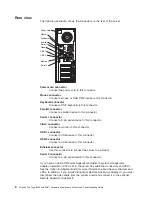
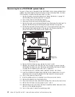
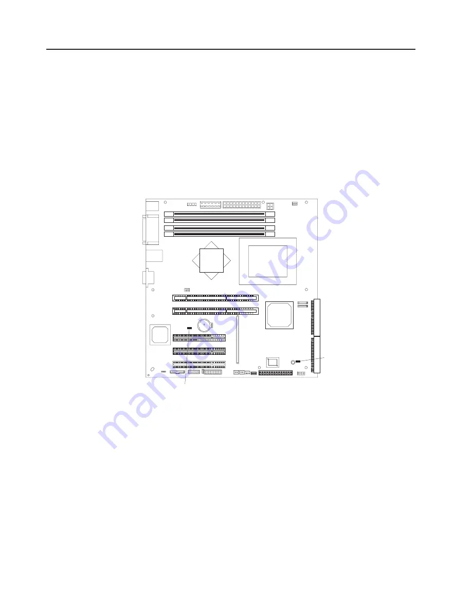
5. Locate the boot block recovery jumper (JP1) on the system board, removing
any adapters that impede access to the jumper. The following illustration
shows the location of the jumper on the system board.
Boot block
jumper (JP1)
CMOS jumper (JP2)
6. Remove the boot block recovery jumper from pins 1 and 2.
7. Replace any adapters that were removed; then, replace the support bracket
and replace the side cover (see “Removing and installing the support bracket”
on page 28 and “Replacing the side cover” on page 50).
8. Connect the server to a power source, keyboard, monitor, and mouse.
9. Insert the POST/BIOS update (flash) diskette into the diskette drive. You can
download a file to create this diskette from http://www.ibm.com/pc/support/.
10. Turn on the server and the monitor.
11. After the update session is completed, turn off the server and monitor.
12. Remove the diskette from the diskette drive.
13. Disconnect all power cords and external cables; then, remove the server cover.
14. Return the boot block recovery jumper to pins 1 and 2.
15. Reinstall the server cover; then, reconnect all external cables and power cords
and turn on the peripheral devices.
16. Turn on the server to restart the operating system.
20
xSeries 206 Type 8482 and 8487: Hardware Maintenance Manual and Troubleshooting Guide
Summary of Contents for 84875MU
Page 1: ...xSeries 206 Type 8482 and 8487 Hardware Maintenance Manual and Troubleshooting Guide...
Page 2: ......
Page 3: ...xSeries 206 Type 8482 and 8487 Hardware Maintenance Manual and Troubleshooting Guide...
Page 6: ...iv xSeries 206 Type 8482 and 8487 Hardware Maintenance Manual and Troubleshooting Guide...
Page 10: ...viii xSeries 206 Type 8482 and 8487 Hardware Maintenance Manual and Troubleshooting Guide...
Page 22: ...12 xSeries 206 Type 8482 and 8487 Hardware Maintenance Manual and Troubleshooting Guide...
Page 68: ...58 xSeries 206 Type 8482 and 8487 Hardware Maintenance Manual and Troubleshooting Guide...
Page 86: ...76 xSeries 206 Type 8482 and 8487 Hardware Maintenance Manual and Troubleshooting Guide...
Page 127: ...Appendix B Related service information 117...
Page 128: ...118 xSeries 206 Type 8482 and 8487 Hardware Maintenance Manual and Troubleshooting Guide...
Page 129: ...Appendix B Related service information 119...
Page 130: ...120 xSeries 206 Type 8482 and 8487 Hardware Maintenance Manual and Troubleshooting Guide...
Page 131: ...Appendix B Related service information 121...
Page 132: ...122 xSeries 206 Type 8482 and 8487 Hardware Maintenance Manual and Troubleshooting Guide...
Page 133: ...Appendix B Related service information 123...
Page 143: ...Appendix B Related service information 133...
Page 144: ...134 xSeries 206 Type 8482 and 8487 Hardware Maintenance Manual and Troubleshooting Guide...
Page 145: ...Appendix B Related service information 135...
Page 146: ...136 xSeries 206 Type 8482 and 8487 Hardware Maintenance Manual and Troubleshooting Guide...
Page 150: ...140 xSeries 206 Type 8482 and 8487 Hardware Maintenance Manual and Troubleshooting Guide...
Page 159: ......
Page 160: ...Part Number 49Y0092 Printed in USA 1P P N 49Y0092...