background image

assembly


out


of


the


server.


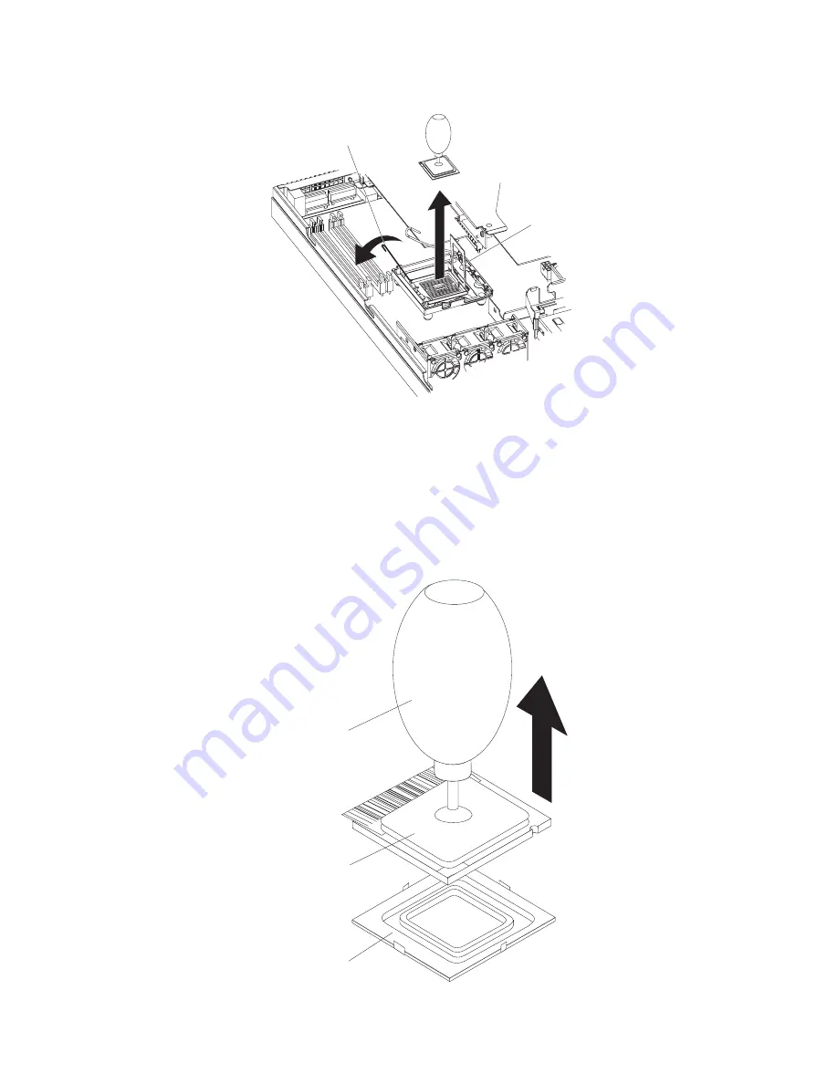
Microprocessor
bracket frame

Microprocessor
release latch


7.


Open


the


microprocessor


release


latch


to


the


fully-open


position.


8.


Open


the


microprocessor


bracket


frame.


Attention:


Use


the


vacuum


tool


provided


with


the


replacement


part


to


remove


the


microprocessor.


Dropping


the


microprocessor


during


removal


can


damage


the


contacts.


Also,


contaminants


on


the


microprocessor


contacts,


such


as


oil


from


your


skin,


can


cause


connection


failures


between


the


contacts


and


the


socket.


9.


Remove


the


microprocessor


using


the


vacuum


tool


and


the


following


procedure:


Vacuum tool

Microprocessor

Socket


Chapter


4.


Removing


and


replacing


server


components


97

Summary of Contents for 306m - eServer xSeries - 8849

Page 1: ...IBM xSeries 306m Types 8849 and 8491 Problem Determination and Service Guide...

Page 2: ......

Page 3: ...IBM xSeries 306m Types 8849 and 8491 Problem Determination and Service Guide...

Page 4: ...page 113 The most recent version of this document is available at http www ibm com support Sixth Edition April 2006 Copyright International Business Machines Corporation 2005 All rights reserved US Go...

Page 5: ...es 11 Error logs 14 POST error codes 15 Checkout procedure 22 About the checkout procedure 22 Performing the checkout procedure 22 Troubleshooting tables 24 CD or DVD drive problems 24 General problem...

Page 6: ...e 86 Installing a CD or DVD drive 86 Removing the operator information panel assembly 87 Installing the operator information panel assembly 88 Removing the power supply 88 Installing the power supply...

Page 7: ...sposal 115 Battery return program 116 Electronic emission notices 117 Federal Communications Commission FCC statement 117 Industry Canada Class A emission compliance statement 117 Australia and New Ze...

Page 8: ...vi IBM xSeries 306m Types 8849 and 8491 Problem Determination and Service Guide...

Page 9: ...tuotteen lue turvaohjeet kohdasta Safety Information Avant d installer ce produit lisez les consignes de s curit Vor der Installation dieses Produkts die Sicherheitshinweise lesen Prima di installare...

Page 10: ...ior cover is not damaged loose or broken and observe any sharp edges 3 Check the power cord v Make sure that the third wire ground connector is in good condition Use a meter to measure third wire grou...

Page 11: ...n the off position v Never assume that power has been disconnected from a circuit Check it to make sure that it has been disconnected v If you have to work on equipment that has exposed electrical cir...

Page 12: ...tion document For example if a caution statement begins with a number 1 translations for that caution statement appear in the Safety Information document under statement 1 Be sure to read all caution...

Page 13: ...quipment when there is evidence of fire water or structural damage v Disconnect the attached power cords telecommunications systems networks and modems before you open the device covers unless instruc...

Page 14: ...ON When laser products such as CD ROMs DVD drives fiber optic devices or transmitters are installed note the following v Do not remove the covers Removing the covers of the laser product could result...

Page 15: ...ower control button on the device and the power switch on the power supply do not turn off the electrical current supplied to the device The device also might have more than one power cord To remove a...

Page 16: ...ese components If you suspect a problem with one of these parts contact a service technician Statement 10 CAUTION Do not place any object weighing more than 82 kg 180 lb on top of rack mounted devices...

Page 17: ...v User s Guide This document is in Portable Document Format PDF on the IBM xSeries Documentation CD It provides general information about the server including information about features and how to con...

Page 18: ...atements are used in this document v Note These notices provide important tips guidance or advice v Important These notices provide information or advice that might help you avoid inconvenient or prob...

Page 19: ...ollers v Serial ATA SATA controller with integrated RAID simple swap SATA models v Serial attached SCSI SAS controller with integrated RAID hot swap SAS SATA models Acoustical noise emissions v Sound...

Page 20: ...ectrical outlet Power control button Press this button to turn the server on and off manually A power control button shield comes installed around the button to prevent the server from being turned of...

Page 21: ...ear of the server Power cord connector Mouse connector Keyboard connector Serial connector Video connector Ethernet 2 connector Ethernet 1 connector USB 1 connector USB 2 connector Power cord connecto...

Page 22: ...System board internal connectors The following illustration shows the internal connectors on the system board 6 IBM xSeries 306m Types 8849 and 8491 Problem Determination and Service Guide...

Page 23: ...and 3 Clear the CMOS data which clears the power on password and administrator password Boot block jumper JP4 v Pins 1 and 2 Normal default v Pins 2 and 3 Recover boot block NMI non maskable interrup...

Page 24: ...System board external connectors The following illustration shows the external connectors on the system board 8 IBM xSeries 306m Types 8849 and 8491 Problem Determination and Service Guide...

Page 25: ...ble 3 System board LEDs LED Description Error LEDs The associated component has failed Baseboard management controller status LED This LED flashes to indicate that the mini BMC is functioning normally...

Page 26: ...I X slots on the riser card assembly PCI X slot 1 64 bit 3 3 V 66 100 MHz PCI X slot 2 64 bit 3 3 V 66 100 MHz The following illustration shows the location of the PCI X and PCI Express slots on the r...

Page 27: ...rimary method of testing the major components of the server The diagnostic programs are on the IBM Enhanced Diagnostics CD See Diagnostic programs messages and error codes on page 38 for more informat...

Page 28: ...um failed Trained service technician only Replace the system board 1 2 1 Programmable interval timer failed Trained service technician only Replace the system board 1 2 2 DMA initialization failed Tra...

Page 29: ...ch time a Battery b Trained service technician only System board 3 1 4 Time of day clock failed 1 Reseat the battery 2 Replace the following components one at a time in the order shown restarting the...

Page 30: ...of the POST error log the system event log and the system event error log from the Configuration Setup Utility program When you are troubleshooting PCI X slots note that the error logs report the PCI...

Page 31: ...on page 61 to determine which components are customer replaceable units CRU and which components are field replaceable units FRU v If an action step is preceded by Trained service technician only tha...

Page 32: ...stem board 162 Device configuration error 1 Run the Configuration Setup Utility program select Load Default Settings and save the settings 2 Reseat the following components one at a time in the order...

Page 33: ...ach time a Battery b Trained service technician only System board 187 VPD serial number not set 1 Run the Configuration Setup Utility program set the serial number and save the configuration 2 Trained...

Page 34: ...d b Trained service technician only System board 1600 Service processor not functioning 1 Reseat the optional Remote Supervisor Adapter II 2 Replace the optional Remote Supervisor Adapter II 178x Fixe...

Page 35: ...the server 2 Run the Configuration Setup Utility program and disable some other resources to make more space available 3 Replace the following components one at a time in the order shown restarting t...

Page 36: ...rd disk drive backplane or back panel d Trained service technician only System board 8603 Pointing device error 1 Reseat the pointing device 2 Replace the following components one at a time in the ord...

Page 37: ...ician only Replace the microprocessor I9990301 Hard disk drive boot sector error 1 Reseat the following components a Hard disk drive b Hard disk drive backplane cable or back panel cables 2 Replace th...

Page 38: ...cluster two or more servers sharing external storage devices If it is part of a cluster you can run all diagnostic programs except the ones that test the storage unit that is a hard disk drive in the...

Page 39: ...rd see System board LEDs on page 36 g Check for the following results v Successful completion of POST see POST on page 11 for more information v Successful completion of startup 3 Did one or more beep...

Page 40: ...n action step is preceded by Trained service technician only that step must be performed only by a trained service technician Symptom Action The CD or DVD drive is not recognized 1 Make sure that v Th...

Page 41: ...service technician only that step must be performed only by a trained service technician Symptom Action Not all drives are recognized by the hard disk drive diagnostic test the Fixed Disk test Remove...

Page 42: ...suggested actions in the order in which they are listed in the Action column until the problem is solved v See Chapter 3 Parts listing Type 8849 or Type 8491 server on page 61 to determine which comp...

Page 43: ...time in the order shown restarting the server each time a Mouse or pointing device b Trained service technician only System board USB keyboard mouse or pointing device problems v Follow the suggested...

Page 44: ...t v The mouse or pointing device USB cable is securely connected to the server the keyboard and mouse or pointing device cables are not reversed and the device drivers are installed correctly v The se...

Page 45: ...MI replace the DIMM v If a DIMM was disabled by the user or by POST run the Configuration Setup Utility program and enable the DIMM 3 Run memory diagnostics see Running the diagnostic programs on page...

Page 46: ...ectly to the correct connector on the rear of the server 2 Make sure that v The server is turned on If there is no power to the server see Power problems on page 33 v The monitor cables are connected...

Page 47: ...ttention Moving a color monitor while it is turned on might cause screen discoloration Move the device and the monitor at least 305 mm 12 in apart and turn on the monitor Notes a To prevent diskette d...

Page 48: ...eserver serverproven compat us v You followed the installation instructions that came with the device and the device is installed correctly v You have not loosened any other installed devices or cable...

Page 49: ...ted v Trained service technician only The microprocessor is correctly installed 3 If you just installed an optional device remove it and restart the server If the server now turns on you might have in...

Page 50: ...the following components a Failing serial device b Serial cable c Remote Supervisor Adapter II if one is present 3 Replace the following components one at a time in the order shown restarting the serv...

Page 51: ...at the server supports the operating system If it does no logical drive is defined RAID servers Run the ServerGuide program and make sure that setup is complete Software problems v Follow the suggeste...

Page 52: ...to the server Video problems See Monitor problems on page 30 System board LEDs The system board has error LEDs for the fans voltage regulator and memory that will help to locate the source of the err...

Page 53: ...ower cord then turn on the server Attention For proper cooling and airflow replace the cover before turning on the server Operating the server for extended periods of time more than 30 minutes with th...

Page 54: ...programs complete the following steps 1 If the server is running turn off the server and all attached devices 2 Turn on all attached devices then turn on the server 3 When the prompt Press F1 For Con...

Page 55: ...art the server and try running the diagnostic programs again If the problem remains replace the component that was being tested when the server stopped The keyboard and mouse pointing device tests ass...

Page 56: ...you must use a diskette that you have formatted yourself this function does not work with preformatted diskettes If the diskette has sufficient space for the test log the diskette can contain other d...

Page 57: ...he riser card assembly 2 Replace the following components one at a time in the order shown restarting the server each time a Riser card assembly b Trained service technician only System board 035 002...

Page 58: ...isk drive backplane cable 2 Replace the hot swap SAS SATA hard disk drive backplane 035 260 0nn System to controller interface failure 1 Reseat the following components a ServeRAID adapter b Riser car...

Page 59: ...rive test error Replace the attached drive 035 273 0nn Adapter Drive error Replace the attached drive 035 274 0nn Adapter Parameters set error 1 Update the RAID controller firmware on the RAID adapter...

Page 60: ...troller firmware on the RAID adapter see Updating the firmware on page 103 2 Reseat the RAID adapter 3 Replace the RAID adapter 035 283 001 Adapter Battery error Replace the battery module on the RAID...

Page 61: ...e technician only System board 075 xxx 000 Failed power supply test Replace the power supply 089 xxx 0nn Failed microprocessor test 1 Make sure that the BIOS code is at the latest level 2 Trained serv...

Page 62: ...backplane or back panel 2 Reseat the hard disk drive 3 Replace the following components in the order shown restarting the server each time a Hard disk drive b Drive cable c Hot swap models SAS SATA c...

Page 63: ...e same time one in each port 4 Replace the loopback plug 405 xxx 000 Failed Ethernet test on Ethernet controller 1 Run the Configuration Setup Utility program and make sure that the Ethernet adapter i...

Page 64: ...ard see Server controls LEDs and connectors on page 4 4 Move the boot block recovery jumper from pins 1 and 2 to pins 2 and 3 5 Replace the server cover 6 Connect the server to the power source keyboa...

Page 65: ...e Installing the system board on page 102 5 Make sure to reinstall all removable components on the system board and reconnect all cables to the system board Reseat the power supply Trained service tec...

Page 66: ...reason unknown Information only ASM reset due to watchdog timeout Information only ASM reset due to x instruction fault y Information only ASM reset was caused by restoring default values Information...

Page 67: ...is cable is damaged replace the power supply 2 Reseat the cables listed in step 1 restarting the server after reseating all cables DHCP failure no IP assigned RETRYING rc xxx count yyy Information onl...

Page 68: ...y LAN Ethernet interface is no longer active Information only LAN Ethernet interface is now active Information only LAN Telnet tamper triggered Possible break in attempt Information only LAN Web Serve...

Page 69: ...ion only RS485 network overload has cleared y or fewer devices are present on the RS485 network Information only Retried alert accepted from system x type y sender s ID z Information only Running the...

Page 70: ...VRM 1 1 Trained service technician only Reseat the microprocessor 2 Replace the following components one at a time in the order shown restarting the server each time a Trained service technician only...

Page 71: ...nly Power supply 2 Replace the following components one at a time in the order shown restarting the server each time a Trained service technician only System board b Trained service technician only Mi...

Page 72: ...technician only System board b Trained service technician only Power supply 2 Trained service technician only Replace the system board System shutoff due to VRM 1 over voltage 1 Trained service techn...

Page 73: ...ans have good airflow and are not obstructed 2 Trained service technician only Reseat the system board 3 Trained service technician only Replace the system board System x started a RS485 connection wi...

Page 74: ...the integrated Ethernet controller manually to match the speed and duplex mode of the hub v Check the Ethernet controller LEDs on the rear panel of the server These LEDs indicate whether there is a pr...

Page 75: ...ives v Memory modules The minimum configuration requirement is 512 MB one 512 MB DIMM in DIMM slot 1 4 Turn on the server If the problem is solved when you remove an adapter from the server but the pr...

Page 76: ...oses consider them identical only if all the following factors are exactly the same in all the servers v Machine type and model v BIOS level v Memory amount type and configuration v Adapters and attac...

Page 77: ...ype 8491 servers To check for an updated parts listing on the Web complete the following steps 1 Go to http www ibm com support 2 Under Search technical support type 8863 and click Search 3 Under Docu...

Page 78: ...to do so in this publication or by IBM Service See the illustration on page 89 for the location of the air deflector in the server An air deflector comes in Misc kit 2 in the following list 62 IBM xS...

Page 79: ...s 5 SAS SATA controller card hot swap models models 1Ax 20x 3Ax 40x 50x 39M4341 6 System board assembly all models except models B2x G2x G4x H2x H4x J2x 39M4339 6 System board assembly B2x G2x G4x H2x...

Page 80: ...r 3 0 GHz 1M models 10x 1Ax 39M6286 20 Microprocessor 3 0 GHz 800 MHz 2MB model B2x 40K9236 20 Microprocessor 3 0 GHz 800 MHz 4MB models H2x H4x 40K9241 20 Microprocessor 3 2 GHz 800 MHz 4MB model J2x...

Page 81: ...the power cord and plug with a properly grounded outlet IBM power cords used in the United States and Canada are listed by Underwriter s Laboratories UL and certified by the Canadian Standards Associ...

Page 82: ...y Turkmenistan Ukraine Upper Volta Uzbekistan Vanuatu Vietnam Wallis and Futuna Yugoslavia Federal Republic of Zaire 13F9997 Denmark 14F0015 Bangladesh Lesotho Macao Maldives Namibia Nepal Pakistan Sa...

Page 83: ...Islands Canada Cayman Islands Colombia Costa Rica Cuba Dominican Republic Ecuador El Salvador Guam Guatemala Haiti Honduras Jamaica Mexico Micronesia Federal States of Netherlands Antilles Nicaragua P...

Page 84: ...68 IBM xSeries 306m Types 8849 and 8491 Problem Determination and Service Guide...

Page 85: ...ved make sure that no one is near the server and that no other objects have been left inside the server v Do not attempt to lift an object that you think is too heavy for you If you have to lift a hea...

Page 86: ...f the air deflector in the server Working inside the server with the power on Attention Static electricity that is released to internal server components when the server is powered on might cause the...

Page 87: ...is still in its static protective package touch it to an unpainted metal part on the outside of the server for at least 2 seconds This drains static electricity from the package and from your body v R...

Page 88: ...ing on the server To remove the cover complete the following steps 1 Read the safety information that begins on page vii and Installation guidelines on page 69 2 Turn off the server and all peripheral...

Page 89: ...nstall the cover and bezel complete the following steps 1 Make sure that all internal cables are correctly routed 2 Set the cover on top of the server so that approximately 13 mm 0 5 inch extends from...

Page 90: ...is either a PCI X or a PCI Express slot 1 Read the safety information that begins on page vii and Installation guidelines on page 69 2 Turn off the server and peripheral devices and disconnect the pow...

Page 91: ...s the adapter slots v Depending on the riser card assembly in the server the server contains either two peripheral component interconnect extended PCI X adapter slots or one PCI X slot and one PCI Exp...

Page 92: ...er scans the PCI X slots to assign system resources If you have not changed the default startup sequence the server starts the devices in the following order the CD drive first then depending on the m...

Page 93: ...ully align the riser card assembly with the guides on the rear of the server and with the riser card connectors on the system board then press down on the assembly Make sure that the riser card assemb...

Page 94: ...ables 4 Remove the filler panel from the bay 5 Pull the loops of the drive tray toward each other and slide the drive into the server until the drive connects to the back panel 6 Release the loops of...

Page 95: ...egins on page vii and Installation guidelines on page 69 2 Make sure that the server cover is in place and fully closed Attention To maintain proper system cooling do not operate the server for more t...

Page 96: ...o ensure proper cooling and airflow do not operate the server for more than 2 minutes with the cover removed 4 Open the retaining clip on each end of the DIMM connector 5 Lift the DIMM out of the conn...

Page 97: ...ir of DIMMs in DIMM connectors 2 and 4 they do not have to be the same size speed type and technology as the DIMMs that are installed in DIMM connectors 1 and 3 However the size speed type and technol...

Page 98: ...fans To replace any of the five replaceable fans complete the following steps 1 Read the safety information that begins on page vii and Installation guidelines on page 69 2 Turn off the server and all...

Page 99: ...b In the location from which you removed the failed fan route the fan cable into its slot in the fan bracket top c Insert the fan into the bracket d Make sure that each of the blue soft tabs on the f...

Page 100: ...g the riser card assembly on page 91 5 Remove the battery a Use a fingernail to press the top of the battery clip away from the battery The battery pops up when released b Use your thumb and index fin...

Page 101: ...that you can insert it into the socket on the side opposite the battery clip b Press the battery down into the socket until it clicks into place Make sure the battery clip holds the battery securely 3...

Page 102: ...ile pressing the tab pull the drive out of the bay Note You might have to push the right rear corner of the drive toward the front of the server to move the drive initially 4 Remove the retention clip...

Page 103: ...the operator information panel assembly complete the following steps 1 Read the safety information that begins on page vii and Installation guidelines on page 69 2 Turn off the server and peripheral d...

Page 104: ...ble and front USB cable to the operator information panel board 4 Install the cover see Installing the cover on page 73 5 Slide the server into the rack 6 Connect the cables and power cords see Comple...

Page 105: ...e cables from any retention clips that secure them to the chassis Note Note the routing of all power supply cables you will route the power supply cables the same way when you install the power supply...

Page 106: ...into a properly grounded electrical outlet b Make sure that the standby power LED on the system board is lit see System board LEDs on page 9 if the standby power LED is not lit discontinue this proce...

Page 107: ...ve it from the server Place the riser card assembly on a flat static protective surface 6 If you are instructed to return the riser card assembly follow all packaging instructions and use any packagin...

Page 108: ...ure that the riser card assembly is fully seated in the riser card connectors on the system board Removing the SAS SATA backplane or SATA back panel To remove the Serial Attached SCSI SAS backplane wh...

Page 109: ...hen you install a hard disk drive 1 Connect the power cable to the replacement backplane or back panel 2 Slide the backplane or back panel into the card guides making sure not to trap or pinch any nea...

Page 110: ...release the controller 9 Lift the controller off the system board 10 If you are instructed to return the SAS SATA controller follow all packaging instructions and use any packaging materials for ship...

Page 111: ...see Installing the cover on page 73 7 Slide the server into the rack 8 Connect the cables and power cords see Completing the installation in the Installation Guide or User s Guide for cabling instruct...

Page 112: ...f 533 or 800 megatransfers per second MT s v The microprocessor uses an integrated voltage regulator on the system board Removing the microprocessor To remove the microprocessor complete the following...

Page 113: ...with the replacement part to remove the microprocessor Dropping the microprocessor during removal can damage the contacts Also contaminants on the microprocessor contacts such as oil from your skin c...

Page 114: ...sor contacts are fragile handle the microprocessor very carefully 2 Align the microprocessor with the socket note the alignment mark and the position of the notches then carefully place the microproce...

Page 115: ...ect the cables and power cords see Completing the installation in the Installation Guide or User s Guide for cabling instructions 12 Turn on all attached devices and the server Thermal grease The ther...

Page 116: ...processor Note 0 01mL is one tick mark on the syringe If the grease is properly applied approximately half 0 22 mL of the grease will remain in the syringe 6 Install the heat exchanger onto the microp...

Page 117: ...SATA controller see Removing the SAS SATA controller on page 94 and place it on a static protective surface for reinstallation 5 Remove all DIMMs and place them on a static protective surface for rein...

Page 118: ...ssor and microprocessor heat exchanger assembly see Installing the microprocessor on page 98 5 Reconnect to the system board the cables that you disconnected in step 6 of Removing the system board on...

Page 119: ...s contain vital product data VPD code You can select to update the VPD code during the BIOS code update procedure Configuring the server The ServerGuide Setup and Installation CD provides software set...

Page 120: ...following tasks v View configuration information v View and change assignments for devices and I O ports v Set the date and time v Set and change passwords v Set and change the startup characteristics...

Page 121: ...pare drive or initialize drives v SerialSelect Utility Note This choice appears on a hot swap SAS or SATA system only It does not appear on a simple swap SATA system Select this choice to configure th...

Page 122: ...array of independent disks RAID array v View or change the RAID configuration and associated devices Consider the following information when using the Adaptec RAID Configuration Utility programs and S...

Page 123: ...ct Devices and I O Ports Advanced Chipset Control Serial ATA 4 Select SATA Controller Mode Option Change the value to Enhanced 5 Scroll down and select SATA RAID Enable 6 Select Enabled 7 Press Esc th...

Page 124: ...106 The integrated SAS SATA RAID feature comes disabled by default You must enable it and install the device drivers before you can use it The SAS RAID configuration utilities device drivers and infor...

Page 125: ...rt the server Viewing the configuration To view information about the SAS SATA controller complete the following steps 1 Start the SAS SATA Configuration Utility program 2 From the SAS SATA Configurat...

Page 126: ...r then press Enter 6 To change the serial number type sn zzzzzzz where zzzzzzz is the serial number then press Enter 7 To change the asset tag type asset aaaaaaaaaaaaaaaaaaaaaaaaaaaaaaaaa where aaaaaa...

Page 127: ...ation You can solve many problems without outside assistance by following the troubleshooting procedures that IBM provides in the online help or in the documentation that is provided with your IBM pro...

Page 128: ...or information about which products are supported by Support Line in your country or region see http www ibm com services sl products For more information about Support Line and other IBM services see...

Page 129: ...TY OF ANY KIND EITHER EXPRESS OR IMPLIED INCLUDING BUT NOT LIMITED TO THE IMPLIED WARRANTIES OF NON INFRINGEMENT MERCHANTABILITY OR FITNESS FOR A PARTICULAR PURPOSE Some states do not allow disclaimer...

Page 130: ...other countries or both UNIX is a registered trademark of The Open Group in the United States and other countries Java and all Java based trademarks and logos are trademarks of Sun Microsystems Inc i...

Page 131: ...a particular purpose These products are offered and warranted solely by third parties IBM makes no representations or warranties with respect to non IBM products Support if any for the non IBM produc...

Page 132: ...nickel cadmium nickel metal hydride lithium or lithium ion battery Consult your user manual or service manual for specific battery information The battery must be recycled or disposed of properly Rec...

Page 133: ...t cause harmful interference and 2 this device must accept any interference received including interference that may cause undesired operation Industry Canada Class A emission compliance statement Thi...

Page 134: ...lass A warning statement Chinese Class A warning statement Japanese Voluntary Control Council for Interference VCCI statement Power cords For your safety IBM provides a power cord with a grounded atta...

Page 135: ...epublic of Czech Republic Dahomey Djibouti Egypt Equatorial Guinea Eritrea Estonia Ethiopia Finland France French Guyana French Polynesia Germany Greece Guadeloupe Guinea Guinea Bissau Hungary Iceland...

Page 136: ...s of America Venezuela 24P6858 Korea Democratic People s Republic of Korea Republic of 34G0232 Japan 36L8880 Argentina Paraguay Uruguay 49P2078 India 49P2110 Brazil 6952300 Antigua and Barbuda Aruba B...

Page 137: ...d 10 controller Ethernet configuring 105 type 3 SAS SATA configuring 108 Serial ATA configuring 106 107 using the Adaptec RAID Configuration Utility to configure 106 using the SAS SATA Configuration U...

Page 138: ...f 39 hot swap SATA 78 installing 77 78 problems 25 removing 77 hard disk drive continued SAS 78 SCSI See SAS simple swap SATA 78 heat output 3 HostRAID feature for SAS SATA enabling 108 using to confi...

Page 139: ...power cords 65 power problems 33 57 power supply replacing 88 reseating 49 power control button 4 button shield 4 power cord connector 5 power on LED 4 problem isolation tables 24 problems CD ROM DVD...

Page 140: ...8 size 3 slot locations PCI X and PCI Express 10 slot locations PCI X and PCI Express 10 slots 3 software problems 35 specifications 3 statements and notices 2 switches and jumpers 7 system board inte...

Page 141: ......

Page 142: ...Part Number 31R1183 Printed in USA 1P P N 31R1183...

Reviews: