


41
5.3 Details of I/O Signal Functions
An input time constant is provided for the input signals of this controller, in order to prevent malfunction
due to chattering, noise, etc.
Except for certain signals, switching of each input signal will be effected when the signal has been
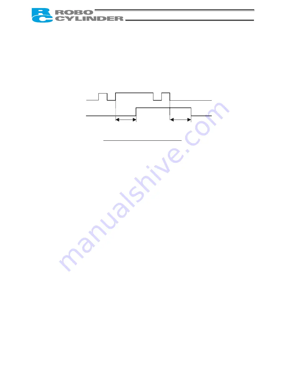
received continuously for at least 6 msec. For example, when an input is switched from OFF to ON, the
controller will only recognize that the input signal is ON after 6 msec. The same applies to switching of
input signals from ON to OFF (Fig. 1).
Fig. 1 Recognition of Input Signal
5.3.1. Details of Each Input Signal
Start (CSTR)
Upon detecting a rise (OFF
→
ON) edge of this signal, the controller will read the target point number as a
binary code consisting of four bits from PC1 to PC8 (or six bits from PC1 to PC32 in the 64-point
positioning pattern), and execute positioning to the target position of the corresponding position data.
Before issuing a start command, all operation parameters such as the target position and speed must be
set in the nonvolatile memory of the controller.
If a start command is issued when home return operation has not been performed yet after the power was
input (the HEND output signal is OFF), the controller will automatically perform home return operation
before positioning to the target position.
Servo ON (SON)
The servo remains ON while this signal is ON.
Use this signal if servo ON/OFF control must be performed by the PLC as part of a safety circuit covering
the entire system.
User parameter No. 21 that defines whether to enable or disable this signal must always be set.
Set “0: [Enable]” if the SON signal is used, or “1: [Disable]” if the signal is not used.
(Note)
If the SON signal is turned OFF during movement in case of error, the actuator will decelerate to
a stop at the emergency-stop torque and then the servo will turn OFF.
Alarm reset (RES)
This signal provides two functions.
(1) Reset the alarm output signal (*ALM) that turned OFF due to an alarm
If an alarm has generated, turn ON this signal after confirming the nature of the alarm.
The controller will reset the alarm upon detection of a rise edge of the RES signal.
(Note)
Certain alarms cannot be reset by the RES signal. For details, refer to 10, “Troubleshooting.”
(2) Cancel the remaining movement when the pause signal is OFF
This function is used when the remaining movement must be cancelled to allow for incremental moves
(movements at a constant increment) from the position where the actuator stopped following a sensor
detection.
6 [msec]
6 [msec]
Input signal
Recognition by controller
Not
recognized
Not recognized