background image

7.0 Maintenance                                                                                                   


_________________________________________________________________________________________ 
CC1132751D                                                                                                                                                        17


7.0 Maintenance 

WARNING ! 


SERVICING  MUST  ONLY  BE  CARRIED-OUT  BY 
TRAINED SERVICE ENGINEERS COMPETENT IN THE 
MAINTENANCE,  MAINS  ELECTRICAL  SUPPLY  AND 
STARTER EQUIPMENT  

7.1 Routine Service 

The  work  listed  must  be  carried-out  at  the  indicated  running 

hours, which must be regarded as a maximum. In dusty, hot or 

humid conditions, more frequent servicing may be necessary. 
On RS units after long periods, speed control unit capacitors and 

cooling fan(s) should be replaced to ensure reliability of the unit. 

7.2 Service Kits 

If  you  are  unable  to  carry-out  the  work  safely  in  the  required 

manner, your Hydrovane Distributor will be pleased to help. 
Use  genuine  parts  and  approved  oils  during  routine  servicing, 

the following service kits are available: 
Oil change kit, 2000 hour/12 months, use KOHR457. 
 Maintenance  kit,  4000  hour/2  year,  use  KMHR457  or 

KMHR457LS.  Serial  numbers:  HR04-000210-1605,  HR05-

000445-1605 & HR07-000790-1601. 
Full  overhaul/top-up  kit,  20000  hour/10  year,  use  KTHR4, 

KTHR5, KTHR7   (inc. KWHR457) use with KMHR kit. 
Additional kits available for full product support are as follows: 
Solenoid  valve  kit,  8000  hour/4  year,  use  KSVDOLHR457, 

KSVSDHR457. 
Contactor  kit,  non-scheduled  item,  use  KCHR457DOL, 

KCHR457RS, KCHR457SD 
Electrical  kit,  20000  hour/10  year,  use  KEHR457DOL, 

KEHR457RS, KEHR457SD 
Oil  Seal  and  Wear  sleeve  kit,  20000  hour/10  year,  use 

KWHR457 (Inc in KT KIT). 
Motor  bearing  kit  (HEBEI  Motor),  20000  hour/10  year,  use 

KBH132 (HR04), KBV132 (HR05/07) 

7.3 Service Instructions 

WARNING ! 


STOP THE COMPRESSOR AND ISOLATE FROM THE 
MAINS ELECTRICAL SUPPLY. LOCK THE ISOLATOR 
IN  THE  OFF  POSITION.  FIT  A  SAFETY  NOTICE 
ADVISING THAT WORK IS BEING CARRIED OUT ON 
THE COMPRESSOR.


CLOSE  THE  AIR  OUTLET  VALVE  TO  ISOLATE  THE 
COMPRESSOR  FROM  THE  AIRLINE  SYSTEM.  FIT  A 
SAFETY  NOTICE  ADVISING  THAT  IT  IS  NOT  TO  BE 
OPENED.


DO  NOT  PROCEED  UNTIL  THE  AIR  PRESSURE 
GAUGE READS ZERO ! 

AVOID  UNNECESSARY  CONTACT  WITH  HOT  OIL 
AND 

COMPONENTS. 

GLOVES 

ARE


RECOMMENDED  IF  DRAINING  OIL  WHEN  THE 
COMPRESSOR IS HOT!


7.4 Panel Removal 

Unlock and open the hinged front door panel to allow removal of 

the top panel. Remove any fixing screws and pull the top panel 

from the location slots and lift clear of the compressor. 

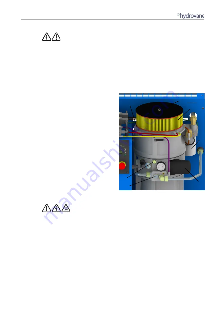
7.5 Oil Filling/Draining (Fig.7.1) 

Remove filler plug (A) with bonded seal (B), remove and retain 

the level plug (C). 
Place a suitable container below the oil drain point, remove drain 

plug (D) with bonded seal (E) and allow oil to drain. 
When  draining  is  complete,  replace  the  drain  plug  and  clean 

away any oil spillages. 
Fill with approved oil to overflow from the level plug. Stop filling, 

replace the level and filler plugs, and clean away any spillage. 
If the oil filter has been replaced, run the compressor for a short 

time (30 seconds) and re-check the oil level.


Fig 7.1 Filler Plug, Air Filter, Separator, Oil Drain 

and Filter


7.6 Oil Filter (Fig 7.1) 

Unscrew  oil  filter  (F)  anti-clockwise,  minimise  spillage  from  the 

canister and discard in a safe manner. 
Using  a  new  filter,  smear  a  small  amount  of  oil  onto  the  seal, 

screw in clockwise, hand tight only. 

7.7 Air Filter (Fig.7.1) 

Remove  M6  Nut  (G)  with  bonded  seal  (H),  remove  the  cover 

plate.  Lift  off  the  air  filter  element  (J)  and  discard  in  a  safe 

manner. 
Using a new air filter element, replace over filter support and fix 

the cover plate back on with, nut and bonded seal. 

7.8 Oil Separator (Fig.7.1) 

Unscrew  oil  separator  (K)  anti-clockwise  and  discard  in  a  safe 

manner.  
Using  a  new  separator,  smear  a  small  amount  of  oil  onto  the 

seal, screw clockwise, hand tight only. 

A B 


D E

G H 

Summary of Contents for HR04

Page 1: ...HR04 HR07 Models User Handbook Original Instructions CC1132751D 10 2018 GB...

Page 2: ......

Page 3: ...3 Compressor Assembly Fig 4 2 12 4 4 Electronic Controller 12 5 0 Operating Instructions 13 5 1 Checking Procedure Before Starting 13 5 2 Operator Control Keys Fig 5 1 13 5 3 Status Display Lights 13...

Page 4: ...17 7 8 Oil Separator Fig 7 1 17 7 9 Oil Cooler Aftercooler Fig 7 2 18 7 10 Cabinet Air Filter Fig 7 2 18 7 11 Electric Motor 18 7 12 Electrical Connections 18 7 13 Service Schedule 18 8 0 Controller...

Page 5: ...odel HR04ER07 4035S000 50Hz model HR04ED07 4035S000 50Hz model HR04ERD07 4035S000 50Hz model HR04E07 5736D005 60Hz model HR04E10 2036D005 60Hz model HR04E10 4035S000 50Hz model HR04ER10 4035S000 50Hz...

Page 6: ...Warning unit is remotely controlled and may start without warning Read the instruction manual Do not operate the machine the machine without the guard being fitted Warning do not start the machine wi...

Page 7: ...ed over a period of time may cause problems that affect the performance and reliability of this compressor Problems may occur when compressors run for short periods on low air demand where they don t...

Page 8: ...ETTINGS Nominal Pressure bar psi 7 0 or 10 0 102 or 145 7 0 102 Minimum Pressure Valve bar psi 5 5 to 6 0 80 to 87 Load Cut in Pressure bar psi 6 5 or 9 5 94 or 138 7 0 102 Unload Cut out Pressure bar...

Page 9: ...low of the compressor Total resistance of the system must not exceed 50 mbar If resistance is expected to be greater fan assistance will be required 3 4 Electrical Connections WARNING CONNECTION TO OR...

Page 10: ...otation is correct by observing pressure rise on the compressor gauge Cooling fan operation is clockwise all RS units have automatic stop start cooling fans that cut in at 85 C 185 F operating tempera...

Page 11: ...ir demands The compressor will load unload and stop start automatically in response to air demand Motor restarts are set to 10 times per hour for single speed units and 30 times for RS units Run on ti...

Page 12: ...d adjacent to the oil filter The compressor is filled and topped up with oil via the oil filler P The sight glass O will be full when oil overflows from the level plug orifice Q Oil is drained from th...

Page 13: ...ssure are viewed here The third row shows status fault and warning messages The HYDROVANE Pro is fitted with two light signals green red Flashing system is ready the motor may start up automatically a...

Page 14: ...sure set point the REVS Reduced Energy Venting System sequence will begin If there is an air demand during the REVS run on time sequence the compressor returns to full load operation If there is no ai...

Page 15: ...IN POINT or p2 TARGET PRESSURE RS e RUN ON TIME f AUTOMATIC OPERATION g ENABLE REMOTE START h TIMER CONTROL i p2 TIMER CONTROL j AUTO RESTART k POWER LOSS TIME l START UP DELAY m DRYER PRE RUN n RS48...

Page 16: ...this is the basis for accurate timer operations Go to the TIMER CONTROL sub menu use the or key to select from seven different timer units The status line of each switching unit is as follows a b c d...

Page 17: ...SAFETY NOTICE ADVISING THAT WORK IS BEING CARRIED OUT ON THE COMPRESSOR CLOSE THE AIR OUTLET VALVE TO ISOLATE THE COMPRESSOR FROM THE AIRLINE SYSTEM FIT A SAFETY NOTICE ADVISING THAT IT IS NOT TO BE...

Page 18: ...special attention to power connections cables connected to contactors and incoming terminals and ensure all earthing wiring is present and undamaged Close the starter panel door and lock with the key...

Page 19: ...d X X X X Check motor conduit cables secure X X X X Check motor for damage X Check motor starter for loose connections X X X X Check motor for vibration X X X X Check flexible control pipes X X X Chec...

Page 20: ...motor for damage X Check motor starter for loose connections X X X Check motor for vibration X X X Check flexible control pipes X X Check oil seal for leakage X X Check drive media key X Check starte...

Page 21: ...t now starts automatically after a previously set time f WARNING START IN Alternating with AFTER DRYER PRE RUN The unit has been switched on and is ready The unit starts automatically after the dryer...

Page 22: ...he Engineering Department Gardner Denver Ltd Web www hydrovaneproducts com www gardnerdenver com E mail sales compair com hydrovane nfo uk gardnerdenver com CC1132751D hydrovane USA 1301 North Euclid...

Page 23: ......

Page 24: ...ons for hydrovane Various Applications Global Expertise Gardner Denver Ltd Claybrook Drive Redditc h Worc estershire B98 ODS UK T 44 0 1527 525522 838200 E hydrovane info uk gardnerdenver com www hydr...

Reviews: