26
-1500/-1700 IHT
REF. Part Name
1 Main Housing
29 Screw
52 Gerotor Assembly
53 O-ring
54 Pump Cover
162 Shim
163 Pin
AUXILIARY PUMP
ASSEMBLY (IF EQUIPPED)
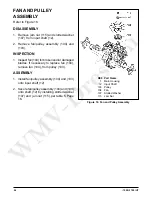
Refer to Figure 20.
DISASSEMBLY
1. Remove two screws (29) from the auxiliary
pump cover (54), and remove the cover
(54).
2. Remove o-ring (53), gerotor assembly (52),
shim (162) and pins (163).
INSPECTION
1. Inspect gerotor assembly (52), pump cov er
(54), for damage or ex ces sive wear.
ASSEMBLY
1. Install gerotor (52) with new o-ring (53) onto
in put shaft (12) (not shown).
2. Install new O-ring (53) into pump cov er
(54).
3. Install pins (163) and shim (162) onto the
pump cover (54).
4. Install cover (54) and secure by installing
two screws (29), per Table 5, Page 16.
Figure 20. Auxiliary Pump Assembly


