background image

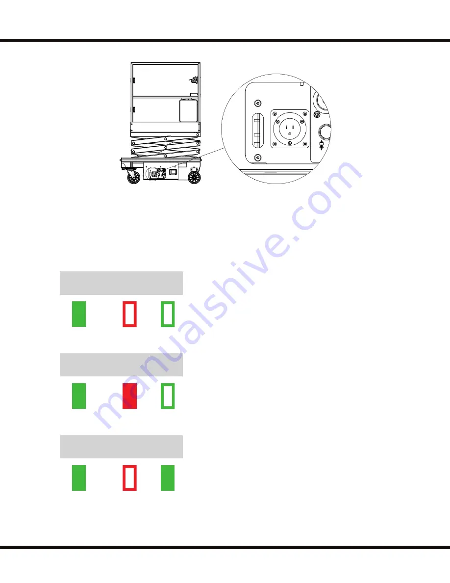
Reading the battery displays 

This display indicates that the power is on but there is no connection 
to a battery. The charger must see approximately five (5) volts on a 
battery to deliver D/C current.

This display indicates that power is on and that the output is delivering 
D/C current to the battery.

This display indicates that power is on and that the output is finished 
charging and is in a float maintenance model.

FIGURE 19: Battery Charger and Light Locations

Battery solution is at its proper strength when the battery is manufactured.  Use distilled water and keep fluid 
up to proper level.  When required, water should be added to battery after charging, unless water level is 
below the plates.

Green LED

(ON)

Red LED

(OFF)

Green LED

(ON)

Red LED

(ON)

Green LED

(OFF)

Green LED

(ON)

Red LED

(OFF)

Green LED

(ON)

POWER

BATTERY 1 STATUS

CHARGING        READY

BATTERY 1 STATUS

CHARGING        READY

POWER

BATTERY 1 STATUS

CHARGING        READY

POWER

Green LED

(OFF)

SECTION 6 

OPERATION

31

OPERATION & SAFETY MANUAL

 PA1.1-S REV A

Summary of Contents for PA-1030

Page 1: ...BY CUSTOM EQUIPMENT LLC OPERATION SAFETY MANUAL MOBILE ELEVATING WORK PLATFORMS ANSI A92 20 CSA B354 6 17 PUSH AROUND SERIES PA 1030 PA1 1 S REV A SERIAL NO ...

Page 2: ...5 webservice hybridlifts com Parts Information 1 262 297 5196 webparts hybridlifts com Register your Hy Brid Lift at www hybridlifts com RegisterOnline htm Register your Hy Brid Lift to Receive product updates and recalls Receive service bulletins product and part recalls and other important notifications Comply with ANSI A92 20 Standards Provide better records for service REGISTERING YOUR MEWP WI...

Page 3: ...cause the manufacturer has no direct control over machine application and operation proper safety practices are the responsibility of the user and all operating personnel The guardrail system around the perimeter of the platform is the fall protection system for manual propelled Mobile Elevating Work Platforms MEWP per the A92 20 CSA B354 6 17 Standards It is prohibited to use an MEWP manufactured...

Page 4: ...N 3 PRODUCT DESCRIPTION 14 3 1 GENERAL 14 SECTION 4 DECALS 16 4 1 DECAL LOCATIONS AND DESCRIPTIONS 16 4 2 DECAL SYMBOLS 18 SECTION 5 TRANSPORT HANDLING STORAGE 22 5 1 PRELIMINARY UNPACKING INSTRUCTIONS AND DEALER INSPECTION 22 5 2 STORAGE 22 5 3 TRANSPORTATION 22 5 4 FORK LIFT POCKETS 22 5 5 LIFTING AND TIE DOWN POINTS 23 SECTION 6 OPERATION 24 6 1 BEFORE YOU OPERATE 24 6 2 LOWER CONTROLS 24 6 3 U...

Page 5: ...s 11 FIGURE 7 Maintenance Lock Use 12 FIGURE 8 Maintenance Lock Storage 12 FIGURE 9 Decal Locations 16 FIGURE 10 Fork Lift Pocket 22 FIGURE 11 Tie Down Points 23 FIGURE 12 Example Sling Lifting 23 FIGURE 13 Center of Gravity 23 FIGURE 14 Base Controls 24 FIGURE 15 Platform Controls 25 FIGURE 16 Bubble Level 26 FIGURE 17 Rear Brake 26 FIGURE 18 Padlock Example 26 FIGURE 19 Battery Charger and Light...

Page 6: ...UNCTION OF CONTROLS Page Section 11 2 5 SAFETY CONTROLS 24 6 1 BEFORE YOU OPERATE 27 6 5 ELEVATING AND LOWERING 1 3 NON OPERATING CHARACTERISTICS FEATURES Page Section 9 2 3 SAFETY FEATURES 13 2 8 SAFETY GUIDELINES 14 15 3 1 GENERAL 16 20 4 DECALS 23 5 5 LIFTING AND TIE DOWN POINTS 22 5 4 FORK LIFT POCKETS 26 6 4 STARTUP SHUTDOWN PUSH AROUND SERIES PA 1030 6 ...

Page 7: ...ING THE BATTERY DEVICES Page Section 9 2 4 SAFETY INDICATOR AND INTERLOCKS 11 2 5 SAFETY CONTROLS 12 2 6 MAINTENANCE LOCK 14 15 3 1 GENERAL 18 20 4 2 DECAL SYMBOLS 22 5 3 TRANSPORTATION 24 6 1 BEFORE YOU OPERATE 26 6 7 CHARGING THE BATTERY 1 4 OPERATING CHARACTERISTICS Page Section 9 2 4 SAFETY INDICATORS AND INTERLOCKS 11 2 5 SAFETY CONTROLS 12 2 6 MAINTENANCE LOCK 14 15 3 1 GENERAL 22 5 3 TRANSP...

Page 8: ... to certain hazards that cannot be protected by mechanical means It is therefore essential that operators be competent careful physically and mentally fit and thoroughly trained in safe operation of this machine Although Custom Equipment LLC conforms to specified ANSI OSHA and CSA it is the responsibility of the owner to instruct operators with the safety requirements made not only by Custom Equip...

Page 9: ...If the chassis is tilted more than 1 5 elevating function is prevented and an alarm sounds Lower the platform and move to a hard level surface before elevating Descent Alarm Lowering Interrupt An audible alarm sounds when the machine is lowering When lowering the platform the platform will stop when the ends of the scissors are approximately 2 inches apart for 3 seconds The beacon light flashes to...

Page 10: ...proaches maximum rating An audible alarm will sound once the rated load has been exceeded See the Operation section of this manual for more detail Automatic Brakes When elevated a brake is automatically applied to the rigid wheels The manual parking brake on the swivel casters should also be used See the Operation section of this manual FIGURE 4 Automatic Brake PUSH AROUND SERIES PA 1030 10 ...

Page 11: ... at the base control that when activated will render the unit inoperable until reset To reset pull the button out See the Operating Controls Indicators section of this handbook for more detail IF PLATFORM SHOULD FAIL TO LOWER DO NOT ATTEMPT TO CLIMB DOWN THE BEAM ASSEMBLY SERIOUS INJURY MAY RESULT HAVE AN EXPERIENCED OPERATOR USE THE EMERGENCY LOWERING PROCEDURE TO SAFELY LOWER THE PLATFORM PUSHIN...

Page 12: ...into position whenever the machine is being serviced in a partially raised position Serious injury and or death could result if maintenance lock is not used properly 2 7 PROPOSITION 65 THIS PRODUCT CONTAINS CHEMICALS KNOWN TO THE STATE OF CALIFORNIA TO CAUSE CANCER AND BIRTH DEFECTS OR OTHER REPRODUCTIVE HARM PUSH AROUND SERIES PA 1030 12 ...

Page 13: ...Never use outdoors Lift is not designed for windy conditions or electrical storms Unit must be on hard level surface before elevating Do not operate on incline or uneven surface You must maintain a clearance between any part of the machine or its load and any electrical line or apparatus Follow local power line clearance regulations DO NOT OPERATE MACHINE NEAR POWER LINES THE PLATFORM AND ENCLOSUR...

Page 14: ...inspect the workplace for environmental hazards such as but not limited to drop offs holes slopes debris floor or overhead obstructions surface wind and weather conditions or presence of unauthorized persons Vibration does not create significant hazards on this machine SPECIFICATIONS PA 1030 Working Height 15 7 ft 4 78 m Platform Height 9 7 ft 2 97 m Stowed Height 68 7 in 174 5 cm Platform Entranc...

Page 15: ...ndoor Use Only Rated Slope Level Surface Tilt Sensor Activated 1 5 Longitudinally 1 5 Latterally Grade ability Stowed Position N A Temperature 4 F to 104 F 20 C to 40 C Vibration 8 2 ft s max 2 5 m s2 max Sound Normal Use Alarms 86 dB Normal Use POWER SYSTEMS DRIVE SYSTEM Proportional Electric Drive Speed Platform Elevated N A Drive Speed Platform Lowered N A Lift Speed Lower Speed 18 20 sec Hydra...

Page 16: ...SECTION 4 DECALS 4 1 DECAL LOCATIONS AND DESCRIPTIONS FIGURE 9 Decal Locations PUSH AROUND SERIES PA 1030 16 ...

Page 17: ...P 65 1 1 9 DE1231 A DECAL SERIES PA 2 1 10 DE1232 A DECAL WEBSITE 2 1 11 DE1243 A DECAL E DOWN CABLE 2 1 12 DE1246 A DECAL MANUAL BOX 1 1 13 DE1248 A DECAL LANYARD ATTACHMENT 1 1 14 DE1249 A DECAL ANNUAL INSPECTION 1 1 15 DE1250 A DECAL SCISSOR CRUSH HAZARD 2 1 16 DE1305 A DECAL MAINT LOCK 1 1 17 DE1309 A DECAL TOE BOARD PA 1030 1 1 18 DE1310 A DECAL CAPACITY 530 1P I WO SO 1 1 19 DE1311 A DECAL L...

Page 18: ...e daily safety checklist Lanyard anchorage point location Capacity 1 person Lanyard anchorage points are for work positioning restraints only Use of fall arrest systems attached to anchorage points on mobile equipment may cause machine to tip resulting in serious injury or death Crushing Hazard Do not enter the space beneath the work platform or scissor structure unless the maintenance lock is in ...

Page 19: ...trical lines and apparatus You must allow for machine sway rock or sag and electrical lines swaying This machine does not provide protection from contact with or proximity to an electrically charged conductor You must maintain a clearance between any part of this machine or its load and any electrical apparatus Follow local power line regulations Death or serious injury will result from contact or...

Page 20: ... For safety and controlled handling it is not recommended to move the unit on a slope greater than 5 Fork pocket Hydraulic oil level Engaging Mechanical Action Enable Switch SECTION 4 DECALS PUSH AROUND SERIES PA 1030 20 ...

Page 21: ...THIS PAGE WAS INTENTIONALLY LEFT BLANK 21 OPERATION SAFETY MANUAL PA1 1 S REV A ...

Page 22: ...to the Pre Delivery Frequent Inspection Checklist in the Maintenance Manual 5 2 STORAGE Lower the work platform to the down position Turn key switch to off position Check entire machine for loose or unsecured items Remove any loose items from machine Apply manual brake lock on rear wheels For safety and controlled handling it is not recommended to move the unit on a slope greater than 5 5 3 TRANSP...

Page 23: ...ts and are provided in the front and rear of the machine for securing the machine on a trailer or truck bed for transport between places of use They may also be used as lift points 5 5 LIFTING AND TIE DOWN POINTS FIGURE 11 Tie Down Points FIGURE 12 Example Sling Lifting FIGURE 13 Center of Gravity 23 OPERATION SAFETY MANUAL PA1 1 S REV A ...

Page 24: ...tton Operation described in section 2 5 2 Power Indicator Light Illuminates when power is on 3 Alarm Operation described in section 6 7 Alarm sounds for descent descent delay or warning that machine is on a slope 4 Key Switch Operation described in section 6 4 5 Elevate Lower Switch Operation described in section 6 5 6 Diagnostic Connection Port 7 Overload Indicator Light Operation described in se...

Page 25: ...e Button Operation described in section 6 5 4 Power Indicator Light Operation described in section 6 6 5 Battery Indicator Overload Indicator Light Operation described in section 6 6 6 Elevate Lower Switch Operation described in section 6 5 SECTION 6 OPERATION 6 3 UPPER CONTROLS AND INDICATORS 25 OPERATION SAFETY MANUAL PA1 1 S REV A ...

Page 26: ...is safe It is not recommended to maneuver the unit on a slope greater than 5 Machine must be on a hard level surface before operation Check that bubble level is centered Engage the manual brakes on the rear casters before elevating the platform Ensure that the key in the lower control panel is in the ON position for the chassis or platform control Enter the work platform in the stowed position usi...

Page 27: ...in the base position To elevate lower push in and hold the enable button While pushing the enable button push the top part of the rocker switch to elevate or the lower part of the rocker switch to lower Power Indicator Light lluminates when controls have power Overload Indicator Light Flashes when attempting to elevate machine more than 10 while overloaded Battery Indicator Light When the overload...

Page 28: ...rt Illustration Meaning Slow Pulse Machine is descending Be aware of bystanders and possible obstructions Medium Pulse Machine is on a slope Lower the platform and move to a level surface before elevating Pulse in sync with Indicator Light Machine is overloaded Remove excess weight SECTION 6 OPERATION PUSH AROUND SERIES PA 1030 28 ...

Page 29: ...THIS PAGE WAS INTENTIONALLY LEFT BLANK 29 OPERATION SAFETY MANUAL PA1 1 S REV A ...

Page 30: ...ep cycle 12 volt battery The care and maintenance of your battery has much to do with how well this unit functions Battery wiring should be checked monthly NOTE The surrounding temperature greatly affects the power reserve within a battery EXAMPLE A battery that is 100 charged at 80 F 27 C drops to 65 at 32 F 0 C At 0 F 18 C this battery will drop to 40 efficiency 6 8 CHARGING THE BATTERY Addition...

Page 31: ... float maintenance model FIGURE 19 Battery Charger and Light Locations Battery solution is at its proper strength when the battery is manufactured Use distilled water and keep fluid up to proper level When required water should be added to battery after charging unless water level is below the plates Green LED ON Red LED OFF Green LED ON Red LED ON Green LED OFF Green LED ON Red LED OFF Green LED ...

Page 32: ...CH SHIFT OR AFTER EVERY SIX TO EIGHT HOURS OF USE FAILURE TO DO SO COULD AFFECT THE SAFETY OF THE OPERATOR Pre Start Inspection Push Around Series Model Serial No Keep inspection records up to date Record and report all discrepancies to your supervisor A dirty machine cannot be properly inspected PUSH AROUND SERIES PA 1030 32 ...

Page 33: ... FUNCTIONAL TESTS Gate closes automatically and latches alignment can be adjusted with screw on toe board or railing Platform Controls Check all switches and push buttons for proper operation Emergency Stop Stops all movement Up Down Button Elevates Lowers Enable button must be pressed Base Controls Check all switches and push buttons for proper operation Emergency Stop Stops all movement Key Swit...

Page 34: ...NOTES PUSH AROUND SERIES PA 1030 34 ...

Page 35: ...NOTES 35 OPERATION SAFETY MANUAL PA1 1 S REV A ...

Page 36: ...Equipment LLC 2647 Highway 175 Richfield WI 53076 U S A 1 262 644 1300 1 262 644 1320 hybridlifts com Hy Brid Lifts is a trademark of Custom Equipment LLC These machines comply with ANSI SIA A92 20 and CSA B354 6 17 Revision Date August 2020 Printed in the U S A 2020 Custom Equipment LLC ...

Reviews: