UNPACKING _________________________________________________________________________________
•
Remove the transport packing and the plastic shrink-wrap the laminator is wrapped in to avoid moisture
penetration.
•
Remove the accessory kit package from the top of the laminator, which includes the necessary tools for
installation.
•
Remove the back table placed on the front table and set aside.
•
Remove the protective film wrapped around the laminator’s front table that is holding the footswitches and back
table.
•
Remove the foam from the footswitches and place a footswitch on each side of the laminator for operator use
while feeding images.
•
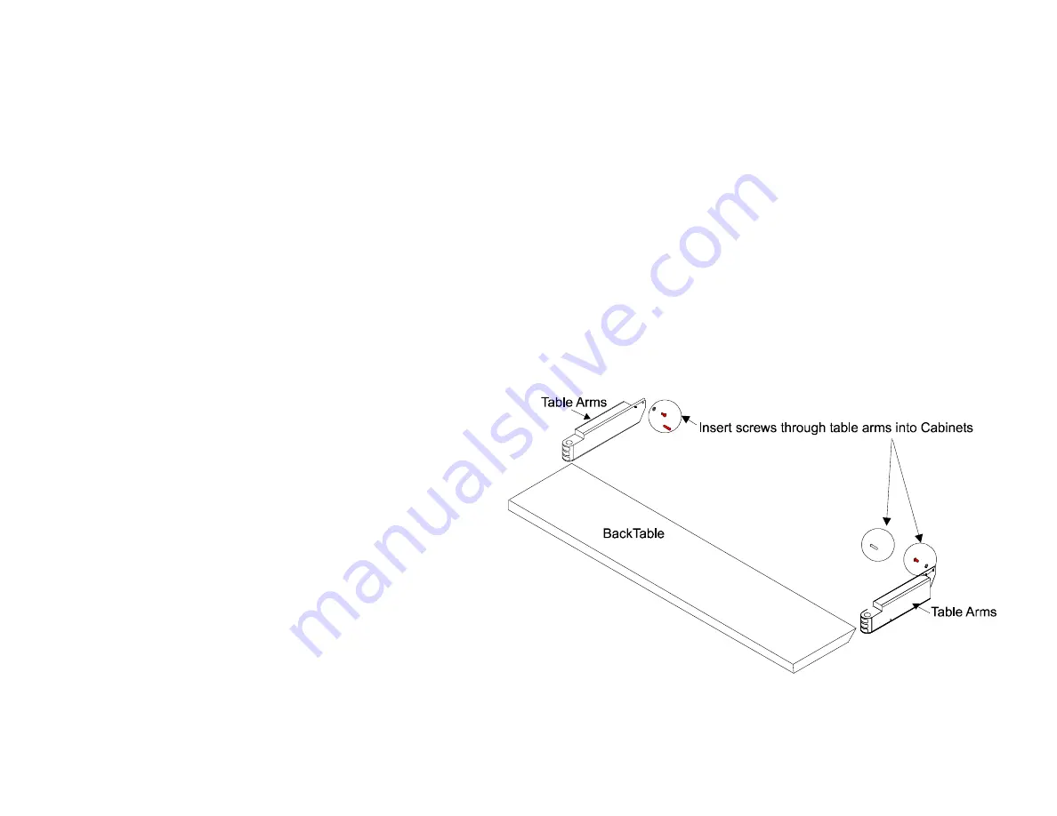
Remove the foam from the back table arms. Using the 3/16” Allen wrench in the accessory pack reattach these
arms to the inside back of the left and right cabinets.
•
Once reattached, unwrap and insert the back table into position.
Figure 2.
Attaching the Back Table Arms and Inserting Table.
•
On the front table, remove the
foam from the ends of the roll
easel shaft and the front table
arms.
•
Fit the roll easel shaft into place
over the front table arms roll
easel stubs.
•
Unpack the Air Compressor and
attach the feet as instructed in
the directions. We recommend
that you use Teflon tape on the
fitting ends of the air compressor
hose to seal for leaks. Insert one
end of the hose into the ‘D’ port
of the compressor. Attach the
female air coupler included in
your Accessory Kit Package onto
the other end of the hose. Connect this end to the male air fitting in the back of the left cabinet. Plug the air
compressor into a standard AC output (110V in U.S., 200–240V in rest of world).


