33
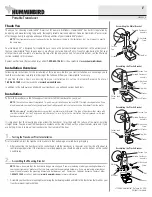
Test & Finish Transducer Installation
Trolling Motor Transducer Installation
Several styles of the transducer are compatible with trolling motor mounting.
If you have a trolling motor bracket, refer to the separate installation
instructions that are included with the bracket.
NOTE:
After trolling motor transducer installation, please perform the final
testing and then finalize the installation (see
Test and Finish the Transducer
Installation
).
Trolling Motor Transducer Options
If you don’t have a trolling motor transducer,
there are several options:
• You may purchase a Trolling Motor Adapter kit
that will allow you to mount the transducer on the
trolling motor.
• You may also exchange your NEW and UNASSEMBLED transducer
(with mounting hardware included) for a trolling motor transducer.
There are also several transducer switches available that support the
following configurations:
• Two control heads with one transducer
• Two transducers with one control head.
NOTE:
Call the Humminbird® Customer Resource Center
1-800-633-1468
for
details and pricing, or visit
humminbird.com
for more information.
Test and Finish the Transducer Installation
When you have installed both the control head, the transducer, and
accessories, and have routed all the cables, you must perform a final test
before locking the transducer in place. Testing should be performed with the
boat in the water, although you can initially confirm basic operation with the
boat out of the water.
1. Press the POWER/LIGHT key once to turn the control head on. There
will be an audible chirp when the key is pressed correctly. If the unit
does not power-up, make sure that the connector holder is fully
seated and that power is available.
2. If all connections are correct and power is available, the control
head will enter Normal operation. If no transducer is detected (or
one is not connected), the unit will go into Simulator mode and will
indicate this by displaying the word Simulator on the control head
display.
NOTE:
The transducer must be submerged in water for reliable transducer
detection.
3. If the bottom is visible on-screen with a digital depth readout, the
unit is working properly. Make sure that the boat is in water greater
than 2 ft (.6 m) but less than the depth capability of the unit, and
that the transducer is fully submerged, since the sonar signal
cannot pass through air.
Summary of Contents for 858c Combo
Page 1: ......
Page 10: ......
Page 159: ...149 Appendix A Side Imaging Transducer Mounting Template XHS 9 HDSI 180 T Appendix A...


