


replaced. If brushes wear rapidly, check for
excessive brush tension and roughness or high
mica on the commutator. Brush spring tension
should be from 24 to 28 ounces.
Starting Motor Disassembl
y
At regular intervals, (the actual time
depending on the type of operation) the
starting motor should be disassembled for a
thorough cleaning and inspection of all
parts. The Bendix drive should be cleaned and
oiled with a penetrating oil as any accumu-
lation of dirt on the drive might restrict
the free movement of the pinion. Never clean
the armature or fields in any degreasing
tank, or grease dissolving materials, since
these may damage the insulation. The commu-
tator should be trued in a lathe if neces-
sary. Replace all parts showing excessive
wear. All wiring connections should be
checked. Rosin flux should be used in making
soldered connections. Acid flux must never
be used on electrical connections. Submit
reassembled unit to NO-LOAD and LOCK tests.
Checking of Improperly Operating
Starting Motor
If the starting motor does not develop rated
torque and cranks the engine slowly or not
at all, check the battery, battery terminals
and connections, and battery cables.
Corroded, frayed, ,or broken cables should
be replaced and loose or dirty connections
corrected. The starting motor switch should
be checked for burned contacts and the switch
replaced if necessary.
If all these are in order, remove the cover
band of the starting motor and inspect the
brushes and commutator. The brushes should
form good contact with the correct brush
spring tension. A dirty commutator can be
cleaned with a strip of No. 00 sandpaper held
against the commutator with a stick while the
starting motor operates. NEVER USE EMERY
CLOTH TO CLEAN COMMUTATOR. If the commutator
is very dirty, or burned, or has high mica,
remove the armature from the cranking motor
and take a cut off the commutator in a lathe.
The mica should be undercut to a depth of
1/32".
If there are burned bars on the commutator,
it may indicate open circuited armature coils
which will prevent proper cranking. Inspect
the soldered connections at the commutator
riser bars. An open armature will show
excessive arcing at the commutator bar which
is open on the no-load test.
Tight or dirty bearings will reduce
armature speed or prevent the armature from
turning. A worn bearing, bent shaft, or loose
field pole screws will allow the armature to
drag on the pole shoes causing slow speed or
failure of the armature to revolve. Check for
these conditions.
If the brushes, brush spring tension, and
commutator appear in good condition, the
battery and external circuit found satisfac-
tory, and the starting motor still does not
operate correctly, it will be necessary to
remove the starting motor for no-load and
torque checks.
NO-LOAD TEST: Connect the starting motor
in series with a battery of the specified
voltage and an ammeter capable of reading
several hundreds amperes. If an R.P.M.
indicator is available, read the armature
24
T E C H N I C A L S E R V I C E M A N U A L
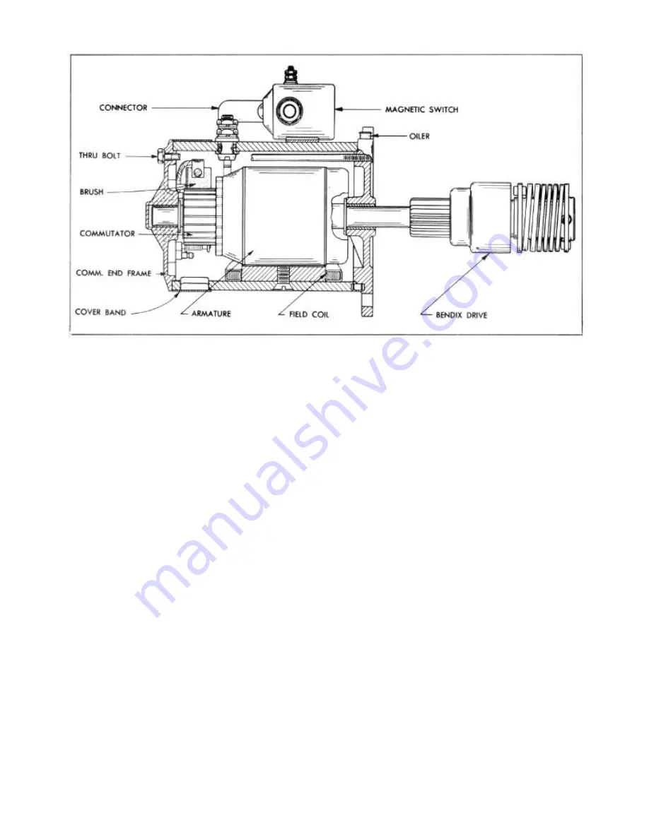
FIGURE 24—
"Rambler" Series Starting Motor (Regular or Overdrive Transmission)
Summary of Contents for 1955 Rambler
Page 1: ......
Page 2: ......
Page 3: ......
Page 4: ......
Page 28: ......
Page 38: ......
Page 42: ......
Page 87: ...46 T E C H N I C A L S E R V I C E M A N U A L...
Page 88: ...ELECTRICAL WIRING DIAGRAMS...
Page 89: ......
Page 90: ......
Page 91: ...ELECTRICAL WIRING DIAGRAMS...
Page 92: ......
Page 93: ......
Page 94: ......
Page 95: ......
Page 96: ......
Page 97: ......
Page 98: ......
Page 99: ......
Page 100: ......
Page 101: ......
Page 102: ......
Page 103: ......
Page 119: ......
Page 127: ......
Page 151: ...OVERDRIVE 5...
Page 165: ......
Page 179: ......
Page 199: ......
Page 200: ...2 TECHNICAL SERVICE MANUAL...
Page 223: ......
Page 243: ......
Page 251: ......
Page 255: ...ALL SEASON AIR CONDITIONING SYSTEM 5 Figure 2 Freon 12 Temperature Pressure Relation Curve...
Page 287: ......
Page 288: ......
Page 289: ......
Page 291: ......
Page 292: ......


