CLUTCH SECTION
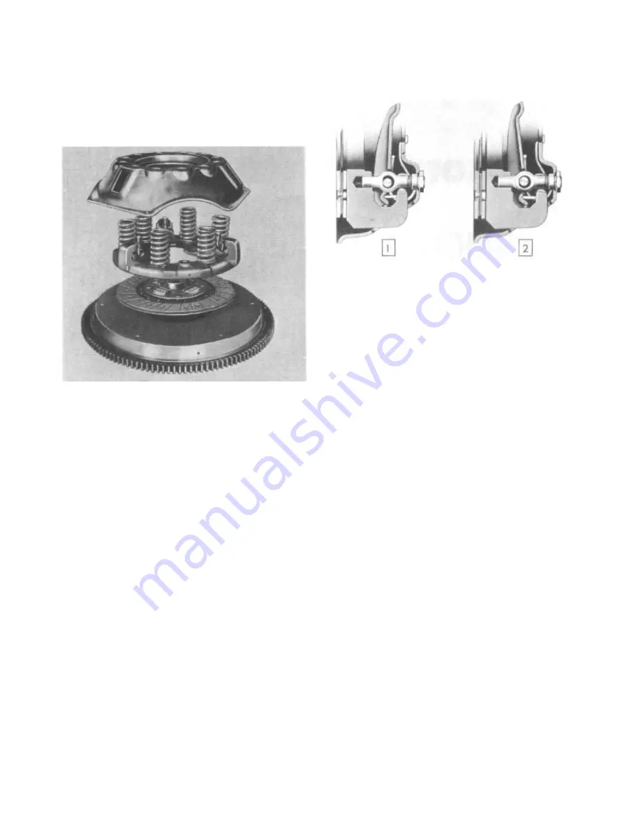
The is a single plate, dry disc type. A steel
covet bolted to the flywheel contains the drive
plate, the pressure plate, levers, and springs
(Fig. 1).
FIGURE 1—Component Parts of Clutch
The clutch drive plate is spring cushioned with
a facing riveted to both sides. The coil springs
around the hub absorb the power shocks and
cushion the driving mechanism.
The clutch throw-out bearing is of the ball
type, packed at time of manufacture, and
requires no further lubrication.
No adjustment for wear is provided in the
clutch itself. An individual adjustment is built
into the clutch cover to adjust the height of
the release levers. This adjusting nut is locked
in position and should never be disturbed unless
the clutch assembly has been disassembled for
the replacement of worn parts.
When the clutch pedal is depressed, the
release bearing is moved toward the flywheel and
contacts the inner ends of the release levers.
Each lever is pivoted on a floating pin which
remains stationary in the lever and rolls across
a short flat portion of the enlarged hole in the
eyebolt. The outer ends of the eyebolts extend
through holes in the stamped cover and are fitted
with adjusting nuts to secure the levers in the
correct position. The outer ends of the release
levers engage the pressure plate lugs by means
of fulcrums, which provide knife-edge contact
between the outer ends of the levers and the lugs
(Fig. 2).
REMOVING THE CLUTCH ASSEMBLY
Always mark the cover, pressure plate and
flywheel on original production assemblies
before removing, so that when they are reassembled
1. Engaged Position
2. Released Position
FIGURE 2—Clutch Lever
they will be in their same relative positions
(Fig. 1).
CAUTION:
When removing the clutch cover
from the flywheel, loosen each cap screw
a few turns until the spring tension on
the cover has been released. The clutch
cover is a steel stamping which could be
sprung by incorrect removal, resulting in
clutch chatter when reused.
CRANKSHAFT PILOT BUSHING
When a assembly is removed from the flywheel,
always inspect the crankshaft pilot bushing
for scoring or loose condition. The bushing
may be removed by using a tap. After the tap
has bottomed in the bore, the bushing will be
forced out. To provide initial lubrication for
this bushing, coat lightly with a short fiber,
medium wheel bearing grease.
CLUTCH DISASSEMBLY
The clutch cover and pressure plate are under
spring tension at all times. Therefore, care
must be exercised when a cover assembly is
disassembled. Place the cover assembly in an
arbor press with a hard wood block under the
pressure plate. Have the block of such a
length that the cover can move down and not
interfere with the blocks. Place a wood block
across the top of the cover so that it rests
on the spring bosses and does not interfere
with the eyebolt adjust. ing nuts (Fig. 3).
Compress the clutch cover in the press
until the clutch release levers are free.
Remove the adjusting nuts (Fig. 3). Release
the press slowly to prevent the springs from
flying out.
CAUTION:
When relieving the spring
pressure, be sure the cover does not
stick on the pressure plate bosses.
Summary of Contents for 1955 Rambler
Page 1: ......
Page 2: ......
Page 3: ......
Page 4: ......
Page 28: ......
Page 38: ......
Page 42: ......
Page 87: ...46 T E C H N I C A L S E R V I C E M A N U A L...
Page 88: ...ELECTRICAL WIRING DIAGRAMS...
Page 89: ......
Page 90: ......
Page 91: ...ELECTRICAL WIRING DIAGRAMS...
Page 92: ......
Page 93: ......
Page 94: ......
Page 95: ......
Page 96: ......
Page 97: ......
Page 98: ......
Page 99: ......
Page 100: ......
Page 101: ......
Page 102: ......
Page 103: ......
Page 119: ......
Page 127: ......
Page 151: ...OVERDRIVE 5...
Page 165: ......
Page 179: ......
Page 199: ......
Page 200: ...2 TECHNICAL SERVICE MANUAL...
Page 223: ......
Page 243: ......
Page 251: ......
Page 255: ...ALL SEASON AIR CONDITIONING SYSTEM 5 Figure 2 Freon 12 Temperature Pressure Relation Curve...
Page 287: ......
Page 288: ......
Page 289: ......
Page 291: ......
Page 292: ......


