


E N G I N E V - 8
5
When removing the tappets, they must be
kept in an order that will insure replacement
in their respective operating bores in the
engine because they are select fitted to that
bore. Keep each tappet component group by
itself as all detail components are select
fitted to one another in manufacturing. Only
complete tappet assemblies are supplied for
service replacement.
The tappet assembly should be cleaned in
a solvent to remove all varnish or leaded
deposits. After cleaning, the tappet must be
"leak-down" tested to insure its "zero-lash"
operating ability. Kerosene should be used
for this test. Test the tappet by filling the
body with kerosene and then install the
plunger return spring, plunger assembly, and
push rod socket. Leave out snap ring for
test. Insert the tappet in tappet test tool
J-5978, and check it for "leak-down" by
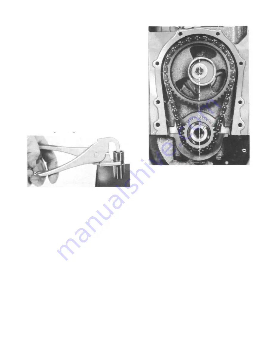
squeezing the handles together (Fig. 11) .
FIGURE 11—
Checking Hydraulic Tappet
"Leak-Down"
If the tappet leaks down rapidly or
collapses immediately, it must be rechecked
and/or replaced with a complete new tappet
assembly. The normal tappet will take approx-
imately 10 seconds or more to "leak- down"
with kerosene. After testing tappets, they
should be prelubricated and assembled in the
engine without an oil charge. They will
normally charge themselves in 3 to 8 minutes
of engine operation.
Tappet Noise
A loud clicking noise is usually the result
of the plunger stuck down below its operating
position or a check valve held open. A light
clicking noise is usually the result of
excessive "leak-down" caused by wear or
slight leakage at the check valve and its
seat.
An intermittent noise at tappet is the
result of dirt or chips stopping the check
valve or a lack of oil flow into the body
because of dirt. A general tappet noise is
in most cases due to a lack of oil volume or
pressure.
The normal tappet plunger operating range
is .140" to .170".
Valve Timing
The correct valve timing is established by
the relation between the sprocket on the
camshaft and the sprocket on the crankshaft.
FIGURE 12—
Properly Installed Timing
Assembly
To obtain the correct valve timing, index
the "0" marks on camshaft and crankshaft
sprockets on a line drawn vertically through
the center line of each shaft (Fig. 12) . To
check the assembly, rotate the crankshaft
until the timing mark on camshaft sprocket
is on a horizontal line at either the 3 or 9
o'clock position. Count the number of links
or pins on the timing chain between timing
marks. You should have 101/2 links and/or 21
pins between timing marks. Each' link con-
tains two pins.
To make an external check of valve
timing, remove the cylinder head covers and
spark plugs. Crank the engine until No. 6
cylinder piston in right bank is on T.D.C.
on compression stroke. This places No. 1
cylinder piston on T.D.C. on the exhaust
stroke valve overlap position. Rotate the
crankshaft counterclockwise. 90°.
Install a dial indicator on the number
one intake valve rocker arm push rod end
(Fig. 13). Crank the engine slowly in
direction of rotation (clockwise) until the
dial indicator indicates push rod movement.
The hydraulic lifter should be fully charged
for this check.
At the time the dial indicator moves, the
ignition timing mark on the vibration damper
should align with the 14° (approx.) position
on the degree quadrant section of the timing
assembly cover. If more than 1/2” variance
Summary of Contents for 1955 Rambler
Page 1: ......
Page 2: ......
Page 3: ......
Page 4: ......
Page 28: ......
Page 38: ......
Page 42: ......
Page 87: ...46 T E C H N I C A L S E R V I C E M A N U A L...
Page 88: ...ELECTRICAL WIRING DIAGRAMS...
Page 89: ......
Page 90: ......
Page 91: ...ELECTRICAL WIRING DIAGRAMS...
Page 92: ......
Page 93: ......
Page 94: ......
Page 95: ......
Page 96: ......
Page 97: ......
Page 98: ......
Page 99: ......
Page 100: ......
Page 101: ......
Page 102: ......
Page 103: ......
Page 119: ......
Page 127: ......
Page 151: ...OVERDRIVE 5...
Page 165: ......
Page 179: ......
Page 199: ......
Page 200: ...2 TECHNICAL SERVICE MANUAL...
Page 223: ......
Page 243: ......
Page 251: ......
Page 255: ...ALL SEASON AIR CONDITIONING SYSTEM 5 Figure 2 Freon 12 Temperature Pressure Relation Curve...
Page 287: ......
Page 288: ......
Page 289: ......
Page 291: ......
Page 292: ......


