


24
TECHNICAL SERVICE MANUAL
system for proper performance.
After the unit operates satisfactorily,
stop engine, close the service valves to the
service valve port fittings by backing the
stems out all the way, disconnect lines, cap
the fittings, and leave the service valves in
this position for normal operation.
Adding Refrigerant—Complete Charge
This operation is performed after a part has
been removed from the system or the complete
charge has been lost through a leak.
Check oil in compressor crankcase. Follow
procedure outlined in "Checking and Adding
Oil."
Add Methanol required at this time at the
compressor oil filler hole. This is done if
the Methanol has not been added to the Freon
in the drum. After Methanol has been added,
install and tighten oil filler plug.
Follow instructions outlined in "Evacuating
the System" procedure. This includes attaching
the gauge set and lines, evacuation, and using
the Freon vapor from the top of the Freon drum
to leak test the system. The use of a slight
charge of Freon vapor at this time will
prevent the loss of a complete charge should
there be a leak.
Common size of refrigerant drums are 3, 5,
10, 25, 50, and 145 pounds. The drums are
ordinarily marked with their tare weight,
which is the weight of the cylinder when
empty. Weighing a cylinder containing refrig-
erant, then subtracting the tare weight, gives
the weight of the contained refrigerant. The
specified complete charge for the system is 4
pounds of Freon-12, for "Hornet" and "Wasp"
Series, and 31/2 pounds for the "Rambler"
Series. To determine the amount of refrigerant
used, weighing the cylinder before and after
charging will enable you to determine the
amount used.
Close the hand valve on the compound gauge
of the gauge set. This will close the gauge
to the center fitting and to the high pressure
gauge.
The discharge service valve is in the
"cracked" position. The suction service valve
is "front seated" or the stem backed all the
way out. Heat may be applied to the drum as
outlined in the procedure of Partially Charg-
ing the System.
Open the Freon drum valve. Charging with
liquid refrigerant is done at the high side
of the compressor at the discharge service
valve. The compressor should not be running.
The drum is held in an inverted position so
the vapor goes to the top of the drum and
exerts pressure on the liquid and forces it
into the system. The liquid refrigerant goes
through the condenser and into the receiver
(Fig. 28).
Close the drum valve after the complete
charge is in the system. This can be readily
determined by the stopping of the hissing
noise as refrigerant is fed into the system
or weighing the drum. Close the hand valve on
the high pressure gauge on the gauge set.
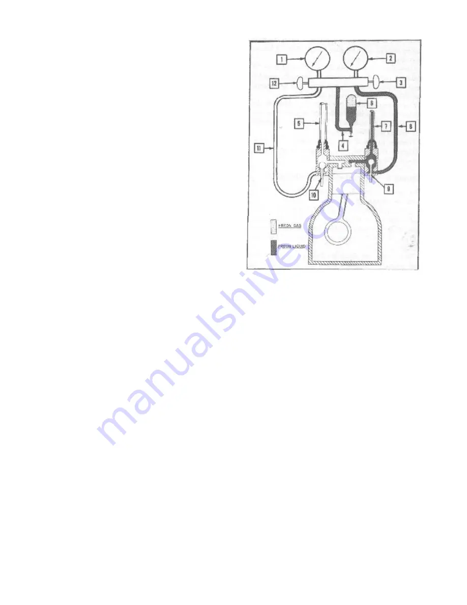
1. Compound Gauge
2. High Pressure Gauge
3. High Pressure Gauge Hand Valve, Open Position
4. Gauge Line, Center Connection to Freon Drum
5. Suction Line, Evaporator to Compressor
6. Freon Drum (4 Pound Charge), Inverted Position
7. Discharge Line, Compressor to Condenser
8. Gauge Line, High Pressure Gauge to Discharge Service
Valve
9. Discharge Service Valve, "Cracked" Position
10. Suction Service Valve, Operating Position
11. Gauge Line, Suction Service Valve to Compound Gauge
12. Compound Gauge Hand Valve, Closed Position
FIGURE 28—
Installing Complete Charge
of Refrigerant
Move the suction valve to the "cracked"
position.
Turn air conditioner in "High" blower. Run
the engine at 1500 to 1800 R.P.M. a few
minutes to check by-pass cycle. Observe the
sight glass and the high and low pressure
gauges. The engine should run from 10 to 15
minutes at idle to normalize the system.
If no bubbles appear at the sight glass
and the pressures are normal, shut off the
engine.
NOTE: Head pressure (high side) should
not exceed 275 pounds at normal room
temperatures.
Excessive head pressure would indicate air
or excessive charge in the system. Purge the
air from the system or release excessive
charge. This method is outlined in the
section on "Air and Moisture in the System"
Again leak test the system. Correct as
required (refer to Leak Test procedure).
Summary of Contents for 1955 Rambler
Page 1: ......
Page 2: ......
Page 3: ......
Page 4: ......
Page 28: ......
Page 38: ......
Page 42: ......
Page 87: ...46 T E C H N I C A L S E R V I C E M A N U A L...
Page 88: ...ELECTRICAL WIRING DIAGRAMS...
Page 89: ......
Page 90: ......
Page 91: ...ELECTRICAL WIRING DIAGRAMS...
Page 92: ......
Page 93: ......
Page 94: ......
Page 95: ......
Page 96: ......
Page 97: ......
Page 98: ......
Page 99: ......
Page 100: ......
Page 101: ......
Page 102: ......
Page 103: ......
Page 119: ......
Page 127: ......
Page 151: ...OVERDRIVE 5...
Page 165: ......
Page 179: ......
Page 199: ......
Page 200: ...2 TECHNICAL SERVICE MANUAL...
Page 223: ......
Page 243: ......
Page 251: ......
Page 255: ...ALL SEASON AIR CONDITIONING SYSTEM 5 Figure 2 Freon 12 Temperature Pressure Relation Curve...
Page 287: ......
Page 288: ......
Page 289: ......
Page 291: ......
Page 292: ......


