


TRANSMISSION
(“Wasp” and “Ranbler”)
19
Install the speedometer drive gear. A Woodruff
key holds the speedometer gear from rotating on
the main shaft. Then install a main shaft snap
ring to hold the speedometer gear in position.
To install the main shaft Oilite bushing on
the "Wasp" Series, assemble the felt oil ring on
it and press the bushing into the rear bearing
cap. The shoulder on the main shaft bushing must
remain 1/4" from the shoulder in the bearing cap
to prevent compressing the felt oil ring (Fig.
25).
When installing the rear bearing cap, note
that the depth of the counter bore in the rear
bearing cap, the thickness of the rear bearing
lock ring, and the rear main shaft snap ring all
control main shaft end play. The rear bearing lock
ring is available in two thicknesses .076" and
.093". The rear main shaft snap ring is available
in four thicknesses .087", .090", .093" and .096".
Use Tool J-1354 rear oil seal installer, "Hornet"
and "Wasp" Series, or J-4485, "Rambler" Series to
install a new rear bearing cap oil seal.
Place the oil slinger on the clutch shaft with
the concave side toward the rear. The front
bearing and lock ring can be installed with Tool
J-2995, together with thrust yoke J-2040 (Fig.
55). Then install the clutch shaft snap ring using
either snap ring pliers or Tool J-2995 Snap Ring
Installing Set.
FIGURE 55—
Installing Clutch. Shaft Bearing
Place a new gasket between the bearing cap and
case and install the bearing cap. The thickness
of this gasket governs clutch shaft end play. The
desired end play is .000".
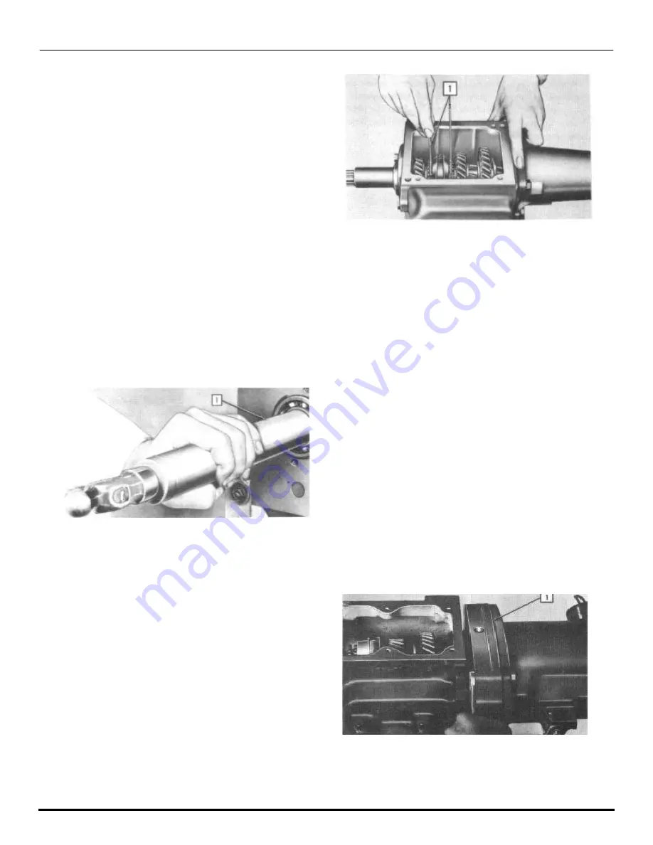
Friction Ring Clearance
Measure the clearance of the friction rings using
friction ring clearance gauge (J-1410). These
clearances should be between .060" to .080". If
less, add steel shims as required between the rear
bearing cap or adapter and transmission case.
Gaskets must be used on both sides of the steel
shim (Fig. 56).
The transmission only requires a final check
by shifting in all gears. Check the operation
carefully, then install the case cover and
gasket, placing the stamping marked "FRONT" to
the front of the case.
1. Tool J-1410
FIGURE 56—
Gauging Front Friction Ring
Clearance. It Should be Between
.060" and .080"
LUBRICATION OF THE
TRANSMISSION
Check the lubricant level of the transmission
every 1,000 miles. The transmission should be
filled to the drain plug level on the right
side. Drain and clean twice a year, or every
10,000 miles, using only flushing oils. Do not
use gasoline, kerosene, steam, etc.
For atmospheric temperatures above 32°F.,
use mineral gear lubricant SAE No. 90 in the
transmission.
Below 32°F., use SAE No. 80.
When difficulty in shifting is experienced
in subzero temperatures, dilute the transmis-
sion oil as required, using light engine oil.
Transmission capacity (U.S.) 11/2 pints
"Rambler" Series. 2-1/4 pints "Wasp" Series.
OVERDRIVE TRANSMISSION
On overdrive equipped transmissions, the over-
haul procedure is the same as outlined in the
standard transmission section with the follow-
ing exceptions.
Remove the bolts that hold the overdrive and
bearing adapter to the transmission case, and
carefully separate the adapter from the trans-
mission. As they are separated, bolt the
adapter to the overdrive case to keep the
overdrive parts in position (Fig. 57).
1. Adapter
FIGURE 57—
Separate the Adapter From the
Transmission Case
Summary of Contents for 1955 Rambler
Page 1: ......
Page 2: ......
Page 3: ......
Page 4: ......
Page 28: ......
Page 38: ......
Page 42: ......
Page 87: ...46 T E C H N I C A L S E R V I C E M A N U A L...
Page 88: ...ELECTRICAL WIRING DIAGRAMS...
Page 89: ......
Page 90: ......
Page 91: ...ELECTRICAL WIRING DIAGRAMS...
Page 92: ......
Page 93: ......
Page 94: ......
Page 95: ......
Page 96: ......
Page 97: ......
Page 98: ......
Page 99: ......
Page 100: ......
Page 101: ......
Page 102: ......
Page 103: ......
Page 119: ......
Page 127: ......
Page 151: ...OVERDRIVE 5...
Page 165: ......
Page 179: ......
Page 199: ......
Page 200: ...2 TECHNICAL SERVICE MANUAL...
Page 223: ......
Page 243: ......
Page 251: ......
Page 255: ...ALL SEASON AIR CONDITIONING SYSTEM 5 Figure 2 Freon 12 Temperature Pressure Relation Curve...
Page 287: ......
Page 288: ......
Page 289: ......
Page 291: ......
Page 292: ......


