P
AGE
6 of 16
S.M.A.R.T. E
MERGENCY
P
HONES
42004-661L2C
f:\standard ioms - current release\42004 instr. manuals\42004-661l2c.doc
11/02
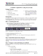
Figure 3. Models 293SL, 293ALSL, and 294ALSL Component Locations
Installing a 297 or 298 Series Phone
1.
Loosen the 6 tamper-resistant screws from the front panel assembly using the GAI-Tronics Model
233 Tamper-Resistant Screwdriver (sold separately).
2.
Prepare the mounting surface for installation of the back box. See Figure 4 for the back box
dimensions.
3.
Install the customer-supplied telephone line surge suppressor, modular wall jack, or in-line coupler, if
applicable.
4.
Remove the tapered plug from the top or bottom cable entry hole in the back box, and install the
customer-supplied telephone line and cable fitting.
5.
Position the back box on the mounting surface, and secure it using the eight #6 flathead screws that
are provided.