P
AGE
5 of 16
S.M.A.R.T. E
MERGENCY
P
HONES
42004-661L2C
f:\standard ioms - current release\42004 instr. manuals\42004-661l2c.doc
11/02
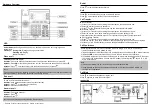
Figure 2. Bottom Entry Conduit Installation
5.
Model 293SL Only:
Create an access hole using a Greenlee-type punch that is equivalent in size to
the conduit diameter. Bottom entry is strongly recommended. Insert a conduit fitting in the access
hole.
CAUTION
Use caution to avoid damage to the telephone PCBA.
Aluminum Enclosure Models:
Thread the conduit into the ½-inch conduit entry. Bottom entry is
strongly recommended. Use the plug provided to close the unused hole. GAI-Tronics recommends
using silicone sealant around and inside all conduit entries and plugs. See Figure 2 for details.
6.
Pull the telephone line through the conduit. Connect the telephone line to the customer-supplied
telephone line surge suppressor (if applicable) and modular jack.
7.
Connect the telephone’s modular plug to a USOC RJ11 modular connector.
Note
: A modular jack may be mounted inside the telephone. Connections directly to TB1 are
acceptable.
8.
Perform the initial programming of the phone. See the Programming section on page 11.
9.
Adjust the speaker levels if necessary. See the Speaker Volume Adjustment section on page 8 for
details.
10.
Complete the installation by attaching the front panel assembly to the rear enclosure using the 4
tamper-resistant screws.


