73
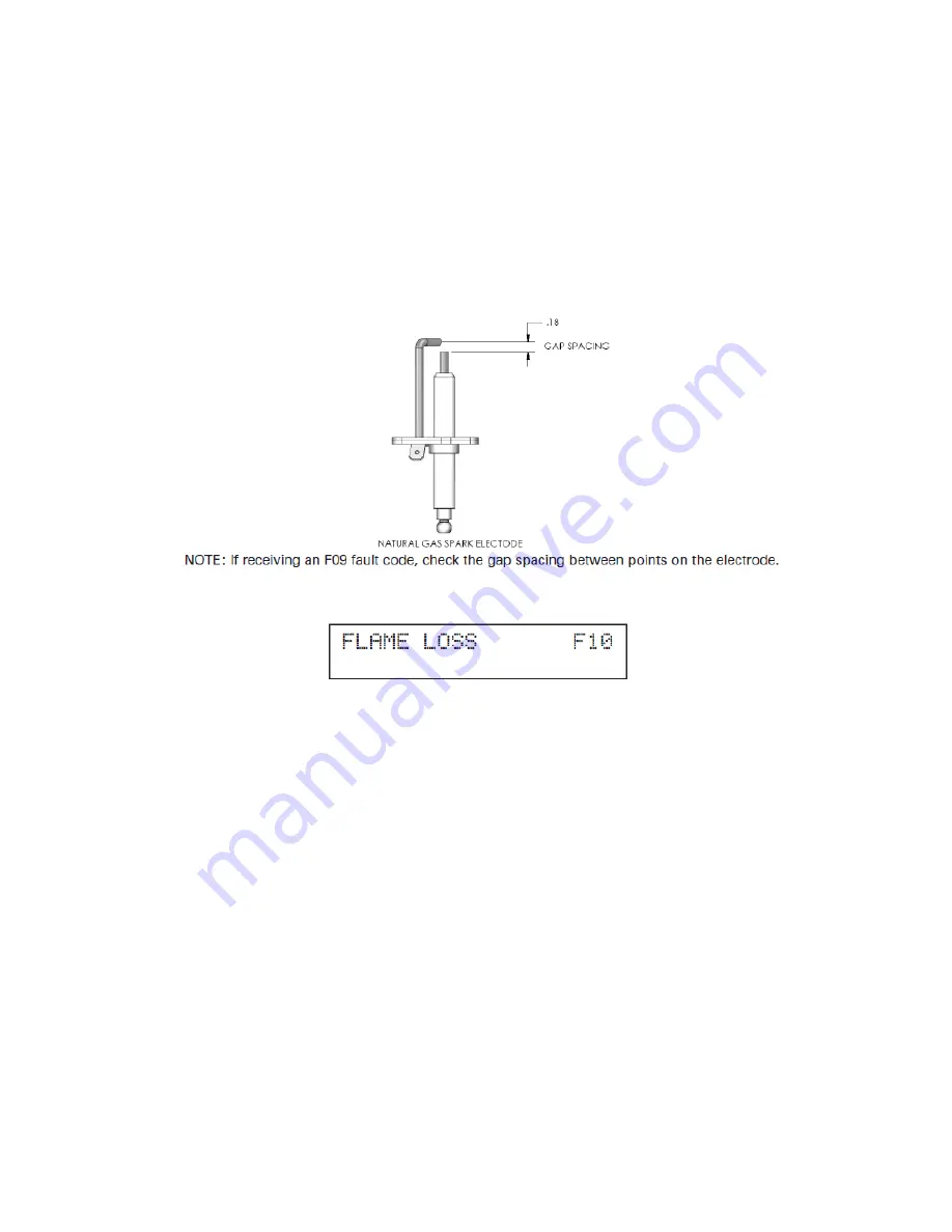
2. If there is no spark, for natural gas units check the spark electrode for the proper gap. Use 2 quarters
together as a gauge to check gap spacing (see Figure 28).
3. Remove any corrosion from the spark electrode and flame rectifier probe.
4. If there is a spark but no flame, check the gas supply to the boiler.
5. If there is a flame, check the flame sensor.
6. Check any flue blockage or condensate blocks.
Figure 28
Fault Code F10
The flame was lost while the unit was lit 3 times during 1 demand call. The red fault light and the word
LOCKOUT flashing on the display indicate a serious safety issue. The unit will not restart until the
technician repairs the cause of flame loss and resets the unit. During this lockout fault, the pump will be
on as indicated on the bottom line of the display.
Remedy:
1. Monitor the gas pressure to the unit while in operation.
2. Assure that the flame is stable when lit.
3. Check to see if the display readout changes from “GAS VALVE ON” to “RUN” within a few seconds
after the boiler ignites
4. Check the FLAME signal on the status display. It should be above 1.0 when the unit is firing.
5. If the signal reads less than 1 microampere, clean the flame rectifier and spark probe.
6. If the problem persists and the ‘FLAME” signal is still less than 1.0, replace the flame probe and spark
igniter probe.
7. The flame signal should be steady after the unit has been firing for 1 minute and is normally at 5.0 to
9.0. If the flame signal is not steady, disassemble the burner door and check the burner and its sealing
gaskets.
Summary of Contents for Versa Hydro PHE130-119
Page 23: ...23 Figure 5 Figure 6 ...
Page 24: ...24 Figure 7 ...
Page 25: ...25 F HYDRONIC PIPING Figure 8 ...
Page 26: ...26 Figure 9 ...
Page 27: ...27 Figure 10 ...
Page 28: ...28 Figure 11 ...
Page 29: ...29 Figure 12 ...
Page 32: ...32 F INTERNAL WIRING Figure 14 Internal connection diagram ...
Page 38: ...38 Figure 17 ...
Page 48: ...48 Figure 25 ...
Page 76: ...76 Figure 29 ...
Page 77: ...77 Figure 30 ...
Page 78: ...78 Figure 31 LP 314 G ...
Page 79: ...79 Figure 32 ...
Page 81: ...81 ...
Page 82: ...82 ...
Page 83: ...83 MAINTENANCE NOTES ...


