50
PART 9: CONTROL OVERVIEW
The control monitors the safety sensors of the heater to assure safe and efficient operation. It has many
features to address configurations associated with hydronic design.
This section addresses the programming features of the control. It is important to fully understand its
capabilities. This section addresses the adjustment of Heater Settings / System Settings / Maintenance
Settings and System Diagnostics to help customize your control. However, the control is programmed
with factory defaults that may already fit your hydronic design and may not require any adjustment at all.
A. NAVIGATION OF THE DISPLAY
The display includes a two-line backlit LCD readout that provides informative messages about heater
operation. Many operating parameters can be viewed and adjusted by using the six buttons on the
display. The function of each button is described below.
RESET
– The RESET button has two functions:
•
Reset any lockout error code.
•
Return the user to the default display screen.
ENTER
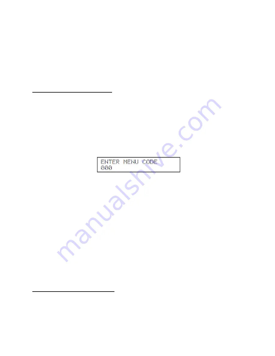
– The ENTER key is used to enter the parameter programming mode. To enter this mode, hold
down the ENTER key for more than 4 seconds. The readout will change to:
One of the zeroes will be blinking. Use the
▲▼
arrow keys to change the blinking digit to the correct
value. Use the
arrow keys to select the next digit to change and again use the
▲▼
keys to change
the value. Repeat until the correct code is entered. Press the
ENTER
key to accept the code. If the code
is correct, the readout will change to the appropriate screen. If the programming code is not accepted the
readout will continue to display as shown above.
The
ENTER
key is also used to enable a parameter for editing. After navigating to the desired parameter,
hold down the
ENTER
key for one second. When the
ENTER
key is released, the parameter value will
begin to blink. The parameter can now be changed using the
▲▼
keys. After the new value is selected,
presses the
ENTER
key for 1 second to lock in the new parameter value. The value will then stop
blinking.
ARROW
Keys – The right and left arrow keys (
)
are used to navigate between the default Display
and Status Display. The
keys are also used in programming modes to change between pro-
grammable parameters. It is recommended you use the Menu Maps in the back of this manual and the
detailed menu instructions printed in this section to help in menu navigation.
ARROW
Keys – The up and down (
▲▼)
arrow keys are used to navigate between the various param-
eters displayed in the menu. After the parameter is enabled for editing by pushing the
ENTER
key, the
▲▼
keys are used to adjust the parameter upward or downward to the desired value.
B. PROGRAMMING THE CONTROL
Program Access
Note: Programming the control is not possible when the heater is firing. Make sure any input (such as the
thermostat) is turned off, so the heater will remain idle and allow programming.
Summary of Contents for Versa Hydro PHE130-119
Page 23: ...23 Figure 5 Figure 6 ...
Page 24: ...24 Figure 7 ...
Page 25: ...25 F HYDRONIC PIPING Figure 8 ...
Page 26: ...26 Figure 9 ...
Page 27: ...27 Figure 10 ...
Page 28: ...28 Figure 11 ...
Page 29: ...29 Figure 12 ...
Page 32: ...32 F INTERNAL WIRING Figure 14 Internal connection diagram ...
Page 38: ...38 Figure 17 ...
Page 48: ...48 Figure 25 ...
Page 76: ...76 Figure 29 ...
Page 77: ...77 Figure 30 ...
Page 78: ...78 Figure 31 LP 314 G ...
Page 79: ...79 Figure 32 ...
Page 81: ...81 ...
Page 82: ...82 ...
Page 83: ...83 MAINTENANCE NOTES ...


