61
C. PURGE AIR FROM HYDRONIC HEATING MODULE
a. Connect to a purge and drain valve location (shown in piping details) and route hose to an area
where water can drain and be seen.
b. Close the ball valves below the purge and drain valve.
c. Close zone isolation valves.
d. Open quick-fill valve on make-up water line.
e. Open purge valve.
f. Open the isolation valves one zone at a time. Allow water to run through the zone and push out
air. Run until no noticeable air flow is present. Close the zone isolation valves and proceed with
the next zone. Follow this procedure until all zones are purged.
g. Close the quick-fill valve and purge valve and remove the hose. Open all isolation valves.
Watch the system pressure rise to correct cold-fill pressure. It is recommended that you put the
pumps into manual operation to assist in purging the circuits.
D. HEATER PUMP CONTROL TO ASSIST IN PURGING AIR FROM SYSTEM LOOPS
Before powering up the control assure the thermostat connection is disconnected on the field connection
board. Apply power to the appliance (Note: The appliance will fire the burner and heat the water inside
the storage tank to the domestic hot water temperature set point). Press
. The display can show the
temperature set point of the appliance. Press the
▼
and
ENTER
keys simultaneously and hold for 1
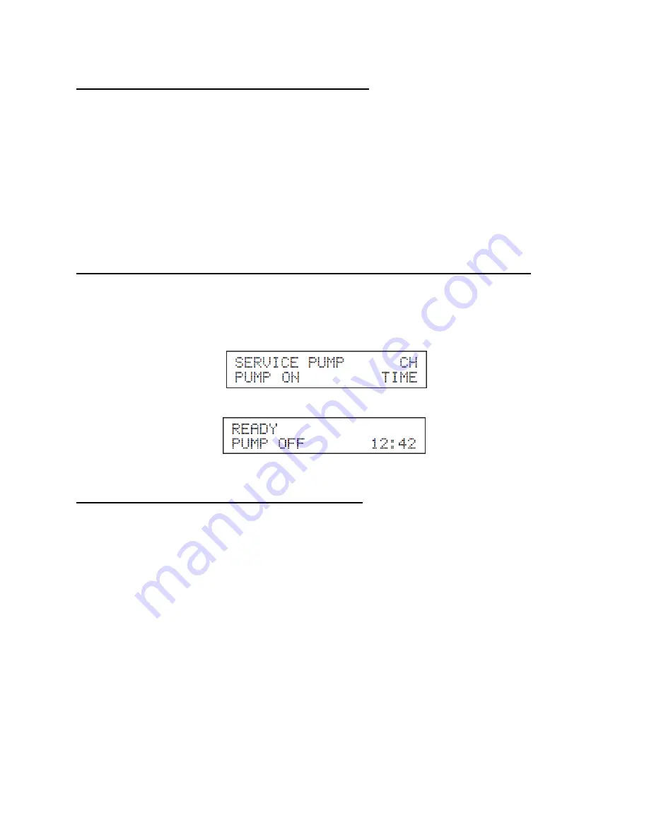
second. The display will read:
The central heating pump will come on. Run pump until all the air has been purged through each circuit. If
you press the
▼▲
keys simultaneously, the central heating pump will shut off. The display will read:
Once the system has been purged of air, the installer can now proceed to program the control and
system design parameters.
E. PROGRAMMING THE TOTAL SYSTEM CONTROL
Before programming the Total System Control to the specific needs of the system, verify that the system
is ready for operation. Be certain that:
•
The Domestic Hot Water system is filled with water that meets the qualifications and all air is
purged.
•
The mixing valve supplied is properly installed.
•
The Hydronic Heating System is filled with water and meets all qualifications and all air is purged.
•
The outdoor reset sensor is installed in a proper location.
•
The electrical power supply is installed by a licensed professional.
•
Turn down thermostats, making sure that they are set so there is no call for heat while
programming.
This section discusses how to program a few of the major sections of the control parameters for
optimum system performance. See the control overview section for more detailed information on
the operation of the display and other parameters.
1. Turn on the main power switch on the top right of the burner cabinet. NOTE: At first startup, the water
in the tank is cold and the burner will ignite. This is normal operation. You can continue to adjust settings
while the burner is running.
Summary of Contents for Versa Hydro PHE130-119
Page 23: ...23 Figure 5 Figure 6 ...
Page 24: ...24 Figure 7 ...
Page 25: ...25 F HYDRONIC PIPING Figure 8 ...
Page 26: ...26 Figure 9 ...
Page 27: ...27 Figure 10 ...
Page 28: ...28 Figure 11 ...
Page 29: ...29 Figure 12 ...
Page 32: ...32 F INTERNAL WIRING Figure 14 Internal connection diagram ...
Page 38: ...38 Figure 17 ...
Page 48: ...48 Figure 25 ...
Page 76: ...76 Figure 29 ...
Page 77: ...77 Figure 30 ...
Page 78: ...78 Figure 31 LP 314 G ...
Page 79: ...79 Figure 32 ...
Page 81: ...81 ...
Page 82: ...82 ...
Page 83: ...83 MAINTENANCE NOTES ...


