9
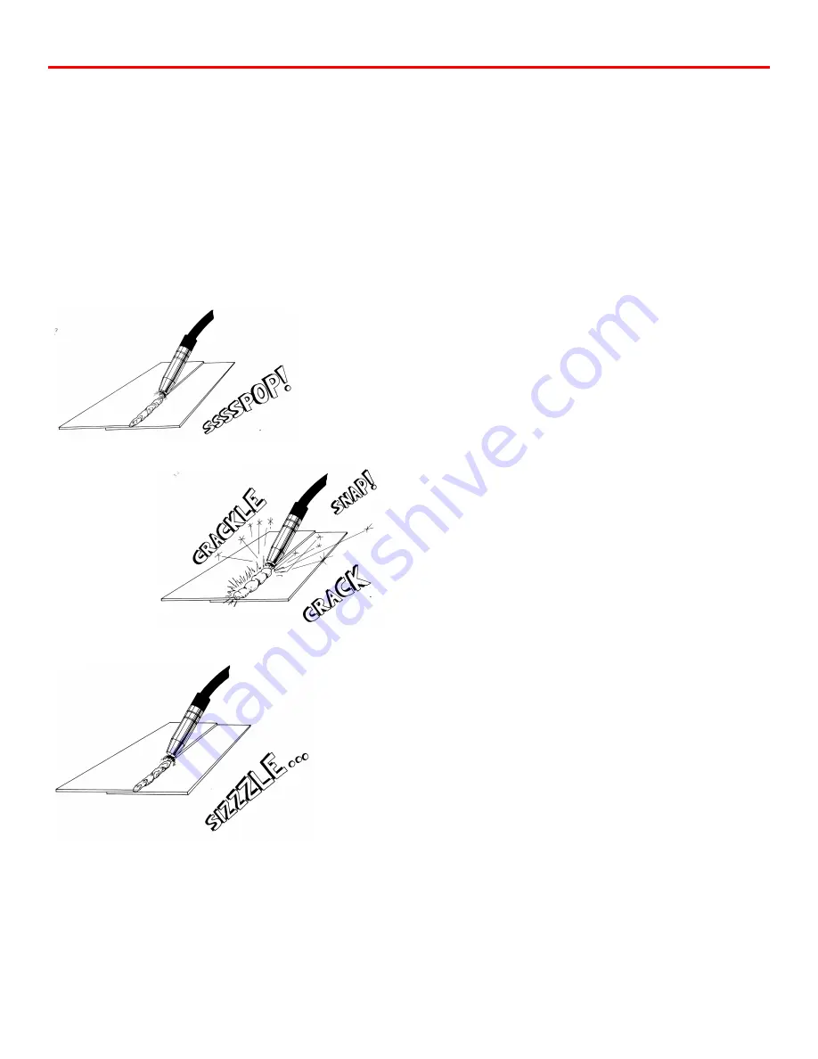
A hissing, blowing sound with a ball of molten wire forming at
the end of the wire and then dropping off indicates the wire feed
rate is too slow (See Fig. X). This means that the wire is
melting before it reaches the metal. A loud, cracking noise with
red hot wire coming out of the gun and the wire pushing the
gun away from the work indicates the wire feed rate is too fast
(See Fig. Y). This means that the wire is melting beyond the
weld and is not melting properly. When “tuned in” properly, a
steady frying noise can be heard (See Fig. Z). This means that
the wire is melting properly, and is melting right at the surface
of the weld.
When tuning in your welding machine, it is best to start with the
wire feed rate too high. On the highest power setting, you may
actually want to start with the wire feed rate set at maximum.
Gradually decrease the wire feed rate until the steady frying
noise is heard. A common problem many people have when
trying to tune the wire feed rate is that they turn the knob too
rapidly. Many people never turn the wire feed rate down low
enough, and then start to increase it again. If the wire feed rate
is slowly decreased, then eventually you will cross the point
where the machine will be tuned in. It is a good idea to practice
tuning in the welding machine. Start with the Voltage setting at
#4, as it has a nice, crisp sizzle. Once you have mastered tuning
in the machine on Voltage Setting #4, practice tuning in the
machine on different Voltage Settings.
It is highly recommended that you practice with your welder at
different Voltage Settings so that you will become familiar with
your welder. This is important to do prior to welding on your
project so you will know which voltage setting to select for an
application.
SEAM WELDING
Install the conical nozzle (Part #15105) on the welding gun.
The conical nozzle is used because it is much easier to see the
welding process due to the taper in the nozzle. Have 1/4" to
1/2" of welding wire protruding from the end of the gas nozzle.
Prior to running a seam weld, it is recommended that tack welds
be placed every 2 to 3 inches along the seam, even closer for
extremely thin panels. Tack welds will help to hold the panel in
place while welding, as well as to prevent panel separation
caused by warpage.
Hold the welding gun at a 45-degree angle and use the edge of
the gas nozzle to hold the two panels together, aim the welding
wire at the spot to be tacked. Momentarily press the trigger
(approximately 1 second) and tack the two panels together. Do
not lift up the welding gun until the weld has set. Tack welding
is done at the same power setting at which seam welding is
done. Select the correct voltage setting based on Chart 3 for the
material you are welding.
When you have the panel tacked into place, you are ready to
seam weld. Once again, have 1/4" to 1/2" of welding wire
protruding from the gas nozzle. The welding gun is generally
held at a 45-degree angle to the work piece. It may also be
tilted at a 45-degree angle to the side. Rest the gun nozzle on
the work piece and have the wire pointing at the spot where the
welding is to begin. Press the trigger and begin welding. It is
important that you can see the welding wire coming out of the
gas nozzle and the small halo formed at the end of the welding
wire where it is melting. This halo will provide the light
necessary to see through your helmet while welding.
Figure x
Figure y
Figure z
Summary of Contents for MTS 160
Page 21: ...21 Wiring Diagram MTS 160...
Page 22: ...Parts Breakdown MTS 160 22...


