10
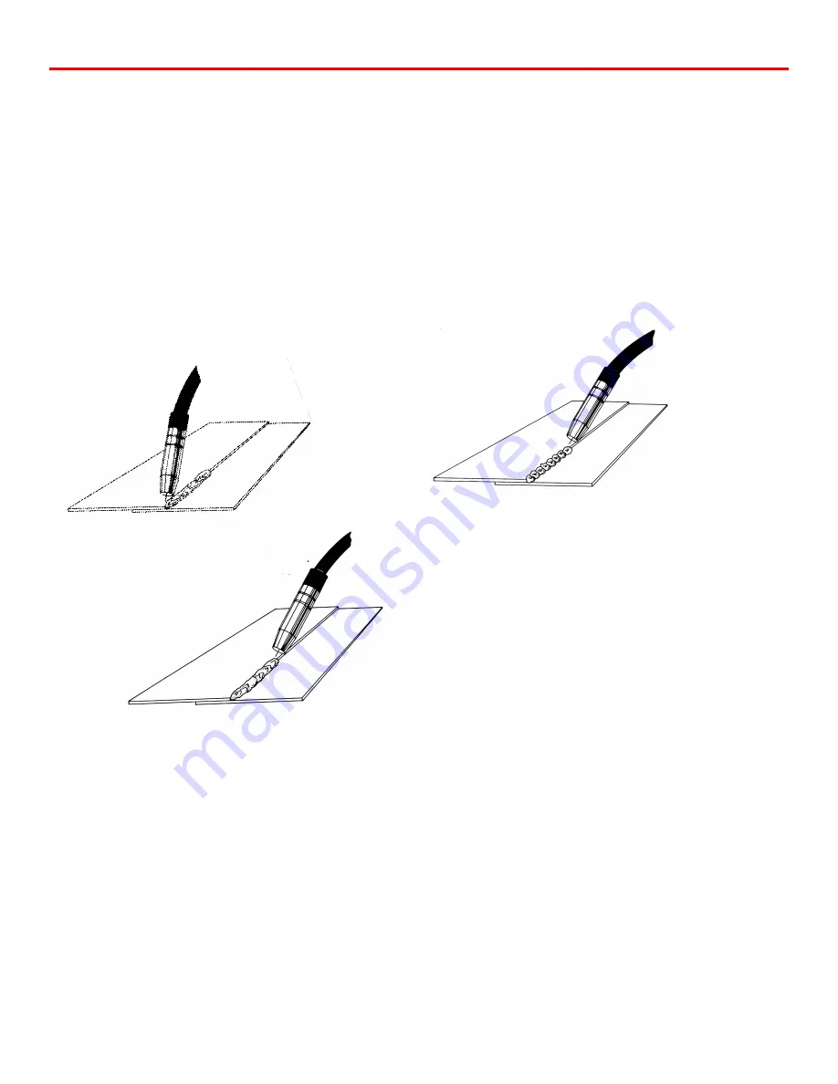
The direction in which the welder travels will affect the
characteristics of the weld. When “pushing the weld” the
welding gun is tilted away from the direction of travel
(See Fig. 4). When “pulling the weld” the welding gun is tilted
toward the direction of travel (See Fig. 5).
As you gain expertise with your welder, you will find that is
possible to reduce warpage when welding sheet metal by
welding at a higher power setting and moving faster along the
seam. In this way, you are reducing the amount of time
welding, therefore reducing the amount of heat which is put into
the panel.
STITCH WELDING
Your HTP MTS 160 can perform a manual stitch weld. Stitch
welding refers to a method of welding where you will weld,
pause, weld, pause and continue in this cycle. This method
produces a welded seam which is actually a series of
overlapping spot welds that give the appearance of “Fish
Scales”. Stitch Welding is recommended for use on very thin
materials, such as thin body panels or rusty exhaust pipe and in
areas where it is desired to keep warpage to a minimum. Stitch
welding is also good for welders who have a problem keeping a
steady hand, or maintaining a constant travel rate.
Stitch welding is performed with the conical nozzle (15105),
small conical nozzle (15108), or the cylindrical nozzle (15104)
and the decision is up to the operator. For manual stitch
welding, the trigger on the welding gun is depressed until 3/16"
diameter puddle of metal is deposited on the workpiece.
Release the trigger and move the welding gun so that the center
of the next puddle will lie on the edge of the first puddle. Wait
for the orange glow from the first puddle to disappear and
deposit the second puddle of metal. Continue this process until
the seam is completed.
For a given thickness of metal, stitch welding is performed at
the same or one power setting lower than seam welding. Stitch
welding can be done on both steel and aluminum, and is
recommended under 120 amps. Stitch welding at higher power
settings can result in serious burnback problems.
SPOT WELDING
Install the spot weld nozzle (Part #15106) on the welding gun.
Using the Punch & Flange Tool (Part #12005 {5/16"} or
#12003 {3/16"}) or the Heavy Duty Hole Punch (#12009)
punch holes in the upper panel to be spotted on. Feed some
welding wire out past the end of the spot weld nozzle. Using
sidecutters, clip the welding wire off flush with the end of the
spot weld prongs. This will aid you in centering the gas nozzle
over the punched hole.
Select the correct voltage setting from the chart 3 (page 8) and
increase by approximately 2 numbers. Tune in the wire feed rate
until the proper frying noise is heard. Reduce the wire feed rate
just until the machine begins to sound out of tune. A slightly
slower wire feed rate will produce flatter spot welds for spot
welds which are vertical down, however, do not reduce the wire
feed rate when performing overhead spot welds. Place the
welding gun over the punched hole so that the welding wire is
centered over the punched hole (See Fig. 7). Depress the
trigger on the welding gun. Release the trigger as soon as the
hole is filled. Examine the spot weld. If the hole is not
completely full, either the welding wire was not centered over
the hole or the trigger was released too soon. If the spot weld is
Figure 5 “Pulling the Weld”
Figure 4 “Pushing the Weld”
Figure 6
“Stitch Welding”
Summary of Contents for MTS 160
Page 21: ...21 Wiring Diagram MTS 160...
Page 22: ...Parts Breakdown MTS 160 22...


