MAINTENANCE AND SERVICE
Introduction
90% of the problems with MIG welders are wire feed/welding
gun related. 98% of these problems are due to owner/operator
abuse, misuse or ignorance.
The welding gun is exposed to the heat and spatter of welding.
The NOZZLE SPRAY (Part #12021) should be sprayed on the
inside of the gas nozzle, contact tip and swan neck with every
use. The function of the nozzle spray is to prevent the spatter
from adhering to the gas nozzle, contact tip and swan neck,
making it easy to keep these parts clean. However, using the
spatter spray does not eliminate the need to frequently clean the
spatter from the gas nozzle. For this reason, HTP has available
a NOZZLE REAMER (Part #12025). The nozzle reamer
makes it very easy to keep your tips and nozzles clean.
Figure 9 shows the early symptoms of spatter build up. The
exterior of the nozzle has arc marks on it from shorting out.
You will also notice the nozzle sticking to the work and
inconsistent weld quality when the nozzle shorts out.
Figure 10 shows a cutaway of a nozzle with spatter build up.
This nozzle is ruined because the operator allowed the spatter to
build up excessively, so the spatter has now welded itself to the
inside of the gas nozzle.
Here are some good rules of thumb to help you select the
correct filler metal:
1) ER70S-6 is generally used for mild steel welding.
2) ER70S-2 is highly recommended for welding 4130
chrome-moly tubing in many applications.
3) ER80S-D2 is recommended for welding 4130 chrome-moly
tubing if a higher strength, less ductile weld is required. If
your weld will be heat treated to obtain optimum strength,
then use a filler metal which matches the chemistry of your
tubing, which neither 70S-2 nor 80S-D2 wires do.
4) Generally speaking, use a 1/16" diameter filler rod for
applications where the material is 1/8" and less. Use a 3/32"
diameter rod for 1/8" and thicker.
The following Filler Rod is available from HTP in 1 lb. tubes
which are tightly sealed to prevent oxidation.
Filler Rod
Part #
Material
308L-035-1
308L Stainless Steel Wire - .035" x 36"
308L-1/16-1
308L Stainless Steel Wire 1/16" X 36"
70S6-1/16-1
ER70S-6 Steel Wire 1/16" X 36"
70S6-3/32-1
ER70S-6 Steel Wire 3/32" X 36"
70S2-1/16-1
ER70S-2 Steel Wire 1/16" X 36"
80SD2-1/16-1
ER80SD-2 Steel Wire 1/16" X 36"
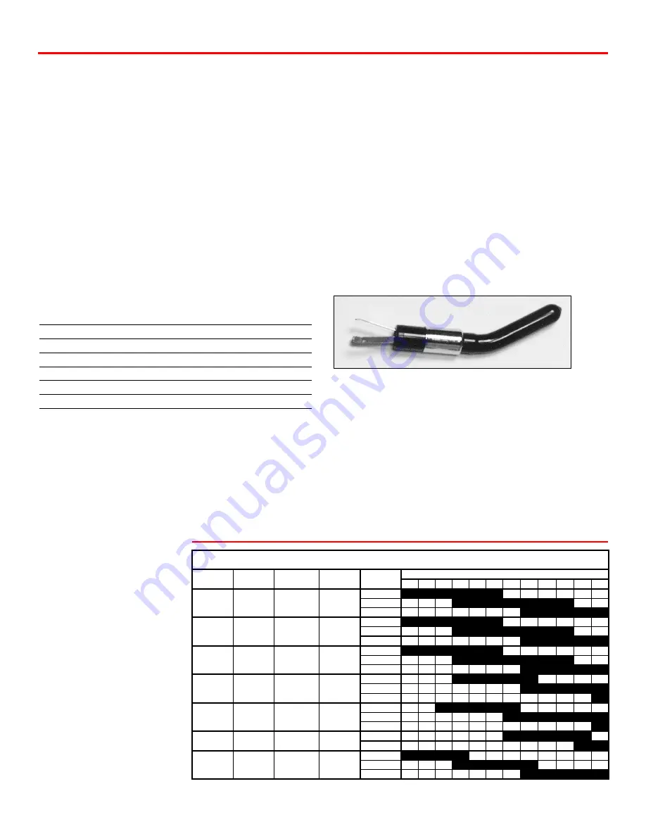
Nozzle Reamer
16
ARC WELDING WITH YOUR MTS 160
You can arc weld with your MTS 160 if you have purchased the
optional electrode holder # 22315-ARCMTS. If you will be
welding Electrode Negative (Straight Polarity) insert the
electrode holder into the negative output receptacle and the
ground cable into the positive output receptacle. If you will be
welding Electrode Positive (Reverse Polarity) insert the electrode
holder into the positive output receptacle and the ground cable
into the negative output receptacle.
Make sure material you are
welding is clean, and attach the
ground cable to the workpiece.
Select the correct rod type,
diameter and amperage for
your application. (See Chart E1)
To strike the arc, drag the
electrode across the work as if
you were trying to strike a match.
Lift the electrode off the work
slightly. If the electrode sticks to
the work, give it a sharp twist to
break it free. If the arc goes out
after it has started, you have lifted
the electrode too high off the
work. Try to incline the electrode
at a 10 deg to 30 deg angle from
perpendicular in the direction of
motion.
40
50
60
70
80
90 100 110 120 130 140 150
6010
EP
DEEP
ALL
3/32"
1/8"
5/32
6011
EP
DEEP
ALL
3/32"
1/8"
5/32
6013
EP,EN
LOW
ALL
3/32"
1/8"
5/32
7014
EP,EN
MEDIUM
ALL
3/32"
1/8"
5/32
7018
EP
LOW
ALL
3/32"
1/8"
5/32
7024
EP,EN
LOW
FLAT
3/32"
1/8"
308L
EP
LOW
ALL
3/32"
1/8"
5/32
Electrode Selection and Amperage Range
Amperage Range
Electrode
Polarity
Penetration
Position
Diameter
Chart E1
Summary of Contents for MTS 160
Page 21: ...21 Wiring Diagram MTS 160...
Page 22: ...Parts Breakdown MTS 160 22...


