25
LP-171 Rev. 3.3.15
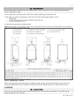
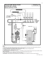
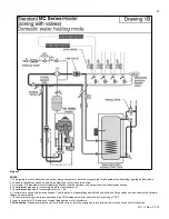
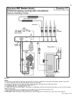
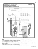
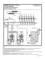
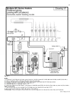
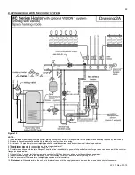
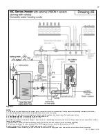
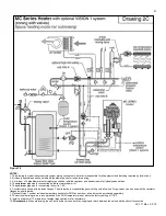
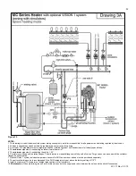
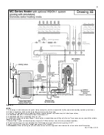
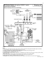
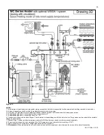
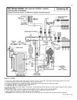
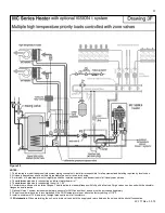
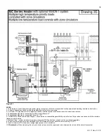
Figure 9
NOTES:
1. This drawing is meant to demonstrate system piping concept only. Installer is responsible for all equipment and detailing required by local codes.
2. All closely spaced tees shall be within 4 pipe diameters center to center spacing.
3. A minimum of 6 pipe diameters of straight pipe shall be installed upstream and downstream of all closely spaced tees.
4. The
minimum
pipe size for connecting an indirect water heater is 1”.
5. The
minimum
pipe size for connecting the unit is 1.25”.
6. Circulators are shown with isolation flanges. The alternative is standard flanges with full port ball valves. Purge valves can be used with the circulator
flanges as an alternative.
7. The anti-scald mixing valve is recommended if the DHW temperature is set above the factory setting of 119
o
F.
8. Install a minimum of 12 diameters of straight pipe upstream of all circulators.
9.
Winterization
: When winterizing the unit, put a drain valve on both the supply and return between the union and the shut-off connection.
Summary of Contents for MC120
Page 21: ...21 LP 171 Rev 3 3 15 M PIPING DETAILS Figure 5 ...
Page 53: ...53 LP 171 Rev 3 3 15 Figure 30 ...
Page 71: ...71 LP 171 Rev 3 3 15 Figure 34 ...
Page 72: ...72 LP 171 Rev 3 3 15 Figure 35 ...
Page 73: ...73 LP 171 Rev 3 3 15 Figure 36 ...
Page 76: ...76 LP 171 Rev 3 3 15 ...
Page 77: ...77 LP 171 Rev 3 3 15 ...

