66
LP-171 Rev. 3.3.15
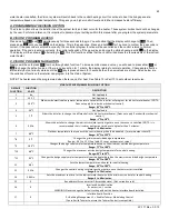
Table 14
926 Control Board FAULT
Code
Description
Remedy
F00
High temperature switch
limit exceeded 194
o
F.
1. Check circulation pump operation.
2. Assure that there is adequate flow through the heater by accessing the status menu and assuring that there
is less than a 50
o
F rise from the return thermister to the supply thermister.
3. Check thermister reading on supply thermister. Replace switch if faulty.
F01
Vent temperature limit
exceeded.
1. Push the red reset button on the vent temperature limit switch.
2. Check module overheat switch. Disconnect the wires plugged into the switch and measure continuity across
the switch.
3. Check the flue temperature during operation using a combustion analyzer.
4. Replace the vent limit switch if faulty. Replace module overheat switch if open.
F02
Interrupted or shorted
supply (outlet) thermister.
1. Check the electrical connection to the thermister on the outlet manifold.
2. If connection is okay, replace thermister.
F03
Interrupted or shorted
return (inlet) thermister.
1. Check the electrical connection to the thermister on the outlet manifold.
2. If connection is okay, replace thermister.
F05
Supply (outlet) temperature
exceeds 230
o
F.
1. Check circulation pump operation.
2. Assure that there is adequate flow through the heater by accessing the status menu and assuring that there
is less than a 50
o
F rise from the return thermister to the supply thermister.
F06
Return (inlet) temperature
exceeds 230
o
F.
1. Check circulation pump operation.
2. Assure that there is adequate flow through the heater by accessing the status menu and assuring that there
is less than a 50
o
F rise from the return thermister to the supply thermister.
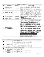
926 CONTROL BOARD ERROR CODES
CODE
DESCRIPTION
DURATION
CORRECTIVE ACTION
FOU
Outdoor sensor is open,
shorted, or outdoor
temperature is below -40
o
F
Until Corrected
1. Disconnect the outdoor sensor from the wiring and measure its resistance.
Compare the measured resistance to the table in this manual to see if it
corresponds to the temperature of the sensor. If the resistance does not
agree with the sensor, replace the sensor.
2. If the resistance is OK, disconnect the sensor wiring from both the boiler
and the sensor and check continuity using an ohmmeter. Repair or replace as
necessary.
E03
The system sensor is open or
shorted
Until Corrected
1. Disconnect the system sensor from the wiring and measure its resistance.
Compare the measured resistance to the table in this manual to see if it
corresponds to the temperature of the sensor. If the resistance does not
agree with the sensor, replace the sensor.
2. If the resistance is OK, disconnect the sensor wiring from both the boiler
and the sensor and check continuity using an ohmmeter. Repair or replace as
necessary.
E19
The line voltage frequency is
out of range
Until Corrected
Inspect power wiring to boiler and repair as necessary. If connected to line
voltage, notify the power company. If connected to an alternate power source
such as generator or inverter, make sure the line voltage frequency supplied
by the device is 60 Hz.
PRO
Water Pressure Switch is
Open
Until Corrected
1. Assure that the system pressure is above 10 psig.
2. Check for leaks in the system piping.
FLU
Blocked Vent Pressure
Switch open, Condensate
Cup Full, Condensate Cup
not present
Until Corrected
1. Check the flue vent to be sure it is not blocked or damaged.
2. Check the blocked vent pressure switch operation by applying a jumper.
(If the switch is not functioning properly, replace it.
3. If the condensate cup is excessively full, check the condensate piping
system for piping and proper drainage. Repair as necessary. If the
condensate cup is not excessively full and is in place, remove the cup and
check the operation of the float switch in the cup. The float should pivot
freely in the cup and the back of the float should contact the stem of the
switch when in the down position.
4. Reinstall the condensate cup. While doing so, check the operation of the
cup-in-place switch. The switch should contact the protrusion on the plastic
socket that the cup is secured into and trip when the cup is snapped into
place.
5. Check to be sure that the 2 pin condensate cup connector is securely
plugged into the socket on the bottom of the heater.
6. If FLU code is still present and the cause not found, check continuity of
wiring from the flue switch to the condensate cup connector (pink wires) and
from the condensate cup connector through the condensate float switch and
condensate cup-in-place switch. These three devices are all wired in series
with each other. Repair any wiring or replace defective components if
necessary.
Do not “Jump Out” any of the devices in this circuit. These
devices ensure product safety and must be in place and
connected at all times of normal operation.
Summary of Contents for MC120
Page 21: ...21 LP 171 Rev 3 3 15 M PIPING DETAILS Figure 5 ...
Page 53: ...53 LP 171 Rev 3 3 15 Figure 30 ...
Page 71: ...71 LP 171 Rev 3 3 15 Figure 34 ...
Page 72: ...72 LP 171 Rev 3 3 15 Figure 35 ...
Page 73: ...73 LP 171 Rev 3 3 15 Figure 36 ...
Page 76: ...76 LP 171 Rev 3 3 15 ...
Page 77: ...77 LP 171 Rev 3 3 15 ...

