97
Main components Replacement Instructions
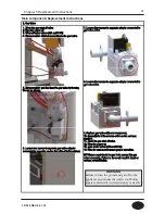
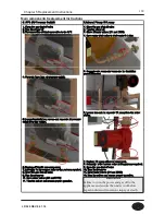
1. Blow Assembly
1. Switch main gas valve to close’s
2. Switch manual power switch to 120V OFF.
3. Switch water valve to close.
4. Separate wire connector attached with gas mixer.
5. Separate nut connected with venturi.
6. Loosen four screws from fan and separate from burner.
7. Separate exhaust pipe from gas mixer.
8. Loosen three screws from the fan and gas mixer.
9. Replace fan with the new part after separating gas
mixer and fan.
10. Attach Fan and gas mixer and tighten with three
screws.
11. Attach fan on the burner and put gas mixer into
exhaust pipe.
12. Fix fan by tightening the four screws in the condition
placed FAN on the burner upper case.
13. Connect venturi and gas pipe and assemble a nut.
14. Connect wire connector on the fan.
15. Switch water valve to open.
16. Switch manual power switch to open
17. Switch main gas valve to open.
18. Test operation
Chapter 5 Replacement Instructions
LP-528 REV. 8.01.14
WARNING
Failure to turn the power and gas off to the
appliance and ensure the unit is cool before
repair could result in serious injury or death.
Summary of Contents for EFTC-140F
Page 3: ...1 LP 528 REV 8 01 14 ...
Page 13: ...11 Operation flow chart Chapter 1 Product Characteristics LP 528 REV 8 01 14 ...
Page 14: ...12 Operation flow chart Chapter 1 Product Characteristics LP 528 REV 8 01 14 ...
Page 15: ...13 Wiring Diagram Chapter 1 Product Characteristics LP 528 REV 8 01 14 ...
Page 16: ...14 Wiring Diagram Chapter 1 Product Characteristics Mixing Valve LP 528 REV 8 01 14 ...
Page 42: ...40 Chapter 3 How to use control panel LP 528 REV 8 01 14 ...
Page 67: ...65 Chapter 4 Troubleshooting 1 Flame Detection LP 528 REV 8 01 14 ...
Page 70: ...68 Error code Chapter 4 Troubleshooting LP 528 REV 8 01 14 ...
Page 71: ...69 Chapter 4 Troubleshooting LP 528 REV 8 01 14 ...
Page 72: ...70 Chapter 4 Troubleshooting LP 528 REV 8 01 14 ...
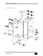
Page 106: ...104 1 Cabinet Replacement Parts Chapter 7 Repair Part Diagram LP 528 REV 8 01 14 ...
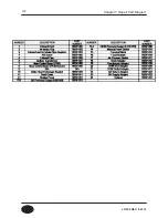
Page 107: ...105 Chapter 7 Repair Part Diagram LP 528 REV 8 01 14 ...
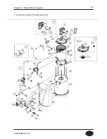
Page 108: ...106 2 Combustion System Replacement Parts Chapter 6 Repair Parts Diagram LP 528 REV 8 01 14 ...
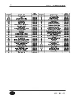
Page 109: ...107 Chapter 7 Repair Part Diagram LP 528 REV 8 01 14 ...
Page 110: ...108 Memo LP 528 REV 8 01 14 ...
Page 111: ...109 Memo LP 528 REV 8 01 14 ...
Page 112: ...110 Memo LP 528 REV 8 01 14 ...

