background image

30

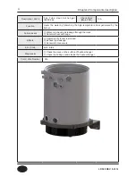
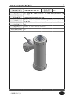
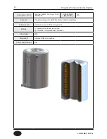
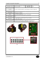
Description / Part #

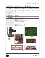
 Burner Assembly: 7855P-064

Check Point

(Main PCB)

 N/A

Function

This component provides the heat source by mixing and combusting air 


and  gas.

Failure Event

① Unable to initialize/sustain combustion

② Soot occurs on the surface of burner

③ Gas leakage occurs from burner

Effects

① Abnormal combustion

② Unstable flame generation

③ Ignition failure

Error Code

N/A

Diagonostic

Visual inspection : Unstable flame conditions during operation.

Color / Wire Number

N/A


Chapter 2 Components description

LP-528 REV. 8.01.14

Summary of Contents for EFTC-140F

Page 1: ...Service Manual EFTC 140F Hot Water Combination Boiler Advanced Heating Hot Water Systems 120 Braley Road East Freetown MA 02717 1 800 323 9651 www htproducts com LP 528 REV 8 01 14 ...

Page 2: ...ry to light any appliance Do not touch any electrical switch do not use any phone in your building Immediately call your gas supplier from a neighbor s phone Follow the gas supplier s instructions If you cannot reach your gas supplier call the fire department Installation and service must be performed by a qualified installer service agency or the gas supplier If the information in these instructi...

Page 3: ...1 LP 528 REV 8 01 14 ...

Page 4: ...ed wire connection 22 Air Pressure switch 23 Condensate Blockage APS 24 Flow sensor 25 Ignition transformer 26 Flame Detection Sensor 27 Gas valve 28 BLDC Fan 29 Burner assembly 30 Fire Tube Heat exchanger 31 Condensate trap 32 Internal DHW storage tank 33 Internal CH DHW circulation pumps 34 DHW Mixing Valve 35 Chapter 3 How to use control panel Function explanation 36 Contol panel 37 LCD Specifi...

Page 5: ...8 View Burner Operating Time X 1000 hr 48 View Ignition cycles X 10 times 49 View Ignition cycles X 10 000 times 49 Pump Condition Display 50 Fault Code History 51 Clear Error Code History 51 System Reset 52 Change DHW Flow Rate Measurement Unit 52 Internal Storage tank Preheating Mode 53 Change maximum outdoor temperature 53 Change minimum outdoor temperature 54 Fan Max RPM Adjustment 54 Fan Min ...

Page 6: ...orage Tank Set Point 62 Internal DHW Storage Tank Differential 63 Delay Time from DHW to CH Mode 63 Internal CH Pump Post Purge Timer 64 Internal CH DHW Pumps Test Mode 64 Chapter 4 Troubleshooting Flame Detection 65 Gas Detection 66 APS Burner Overheat Switch 66 Storage DHW Exhaust Overheat 67 Error code 68 Error Code 10 71 Error Code 11 72 Error Code 16 73 Error Code 20 74 Error Code 28 75 Error...

Page 7: ...de 80 93 Error Code 81 94 Error Code 85 96 Error Code 94 96 Chapter 5 Replacement instructions Blow Assembly 97 Gas Valve 98 Flow Sensor 99 Electronic Mixing Valve 99 APS Air Pressure Switch 100 Inter Primary CH Circulation Pump 100 Internal DHW Storage Tank 101 Flame Detection Sensor 101 Main Controller 102 Ignition Transformer 103 Chapter 6 Components diagram Repair Parts Diagram 104 Memo 108 LP...

Page 8: ...Modulation Metal Fiber Infrared Gas Valve System Air ratio valve Minimum Flow Rate 0 5 GPM Internal Pipe Material Copper Dimensions W15 7 H53 0 D26 8 Shipping Weight 250 lbs Internal Storage Tank Water Capacity 11 Gallon Boiler Heat Exchanger Capacity 4 Gallons Total Water Capacity 15 Gallons Main Controller Control Panel GTX 920C P 920C_CB HTP CH Pressure Min 15 Max 30 PSI DHW Pressure Max 150 PS...

Page 9: ...rovided to Upsize Gas Line B CH supply Adapter 1 C CH return Adapter 1 D DHW outlet Adapter 3 4 E DHW inlet Adapter 3 4 F Condensate Adapter 1 2 G Drain Adapter 1 2 H Exhaust Vent Connection 3 I Intake Pipe Connection 3 Dimensions Chapter 1 Product Characteristics LP 528 REV 8 01 14 ...

Page 10: ...harge Pipe Connector 16 Condensate Outlet Connector 17 Condensate Collector 18 DHW Inlet Connector NO Name of Component 19 Water Mixing valve 20 Water Fill Valve 21 DHW Outlet Connector 22 CH Return Connector 23 CH Supply Connector 24 Main Heating Exchanger Assembly 25 Confirmation Window Flame 26 Gas Inlet Connector 27 Ignition Trans 28 Igniter 29 Gas Valve 30 Air Pressure Sensor 31 Air Intake Pi...

Page 11: ...9 Domestic Hot Water Mode Space Heating Mode Flow chart Chapter 1 Product Characteristics LP 528 REV 8 01 14 ...

Page 12: ...0s 1 0s 3s If normal ignition If flame extinguishes If abnormal ignition Alarm after the 10 trial IGNITION IGNITION IGNITION GAS VALVE GAS VALVE GAS VALVE FLAME DETECTION FLAME DETECTION FLAME DETECTION Chapter 1 Product Characteristics Time chart LP 528 REV 8 01 14 ...

Page 13: ...11 Operation flow chart Chapter 1 Product Characteristics LP 528 REV 8 01 14 ...

Page 14: ...12 Operation flow chart Chapter 1 Product Characteristics LP 528 REV 8 01 14 ...

Page 15: ...13 Wiring Diagram Chapter 1 Product Characteristics LP 528 REV 8 01 14 ...

Page 16: ...14 Wiring Diagram Chapter 1 Product Characteristics Mixing Valve LP 528 REV 8 01 14 ...

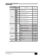
Page 17: ...AN Unuse 2 GND SELV 26VDC 3 VDD SELV 14VDC 4 Fan power start coil SELV 26VDC 5 Fan power end coil SELV 26VDC 6 Fan speed feedback signal SELV 14VDC CN8 SMW250 04 1 MCU ISP GND SELV 5VDC 2 ISP Reset port SELV 5VDC 3 ISP TOOL0 Data port SELV 5VDC 4 VCC SELV 5VDC CN11 LWD1140 16 1 HWL Unuse SELV 12V 8 2 LWL Low Water Level Leakage Sensor SELV 12V 10 3 HD Central Heating Demand SELV 5V 11 4 TH Connect...

Page 18: ...e sensor SELV 5VDC 14 CN14 SMW250 09 1 IWM GND SELV 14VDC 2 IWM Stepper motor position SELV 14VDC 3 VDD SELV 14VDC 4 IWM Stepper motor coil X phase SELV 14VDC 5 IWM Stepper motor coil Y phase SELV 14VDC 6 VDD SELV 14VDC 7 IWM Stepper motor coil X phase SELV 14VDC 8 IWM power IWM Stepper motor coil Y phase SELV 14VDC 9 Not Used CN3 SMW250 06 1 WPS Not Used SELV 5VDC 2 Not Used SELV 5VDC 3 Not Used ...

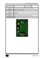
Page 19: ...he combination boiler Failure Event Abnormal main controller operation Effects When the main controller has abnormal condition components may not operate properly Error Code Er 38 Er 70 Diagonostic Check each connection and or wires damage on the PCB Color Wire Number N A Chapter 2 Components description LP 528 REV 8 01 14 ...

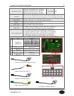
Page 20: ...Wire Number CH Water High Limit Sensor black purple Connector Storage Temperature Sensor black orange Connector Exhaust Temperature Sensor black white Connector DHW Temperature Sensor black yellow Connector CH Supply Temperature Sensor black white Connector NO Item Standard 1 Temperature Resistance Type Idling Condition Temperature Resistance kΩ 0 0 1 10 99 25 0 1 3 906 85 0 1 0 552 3 Blank is for...

Page 21: ...Effects Boiler shuts down if burner plate temperature exceeds the setting temperature Error Code Er 43 Diagonostic Check the connection around the overheat limit switch and use a multi meter to measure resistance If resistance is 0 Ohm replace the switch Check the Dip Switch setting on the Main PCB Check gas orfice Nozzles Size Color Wire Number Temperature switch_burner upper 392 200 orange Conne...

Page 22: ...to prevent dry fire Failure Event Water is not detected at proper level Effects Boiler operation is interrupted Error Code Er 80 Diagonostic Visual inspection wiring connection Check CH pressure gauge minimum CH pressure is 15 PSI Color Wire Number Water level sensor red green Connector Chapter 2 Components description CN11 LP 528 REV 8 01 14 ...

Page 23: ...t Gas leak detection sensor is not operating correctly Effects Risk of explosion and personal injury Error Code Er 40 Diagonostic Follow instruction on first page of installation manual Check for leakage around the gas valve and gas piping by using soapy water Check the burner assembly Color Wire Number N A Chapter 2 Components description LP 528 REV 8 01 14 ...

Page 24: ...n This part is used to jump out circuit Failure Event Jumper is disconected Effects The unit shutsdown Error Code Er 42 Diagonostic Make sure the jumper is properly connected Color Wire Number Jumped Wire Connection white connector Chapter 2 Components description CN11 LP 528 REV 8 01 14 ...

Page 25: ...ame occurs The unit will not ignite Effects Pressure due to exhaust vent blockage will affect the boiler operation Error Code Er 29 Diagonostic Check APS wiring connection Check the hose for blockage or kinking Check exhaust vent for blockage Check APS resistance using a multi meter Color Wire Number Air pressure switch blue connector Chapter 2 Components description CN11 LP 528 REV 8 01 14 ...

Page 26: ...ressure due to condensate line blockage will affect the boiler operation Error Code Er 20 Diagonostic Check Condensate Blockage APS wirring connection Check the hose for blockage or kinking Check the condensate discharge line Check Condensate Blockage APS resistance using a multi meter Color Wire Number Condensate Blockage Switch red connector CN11 Chapter 2 Components description LP 528 REV 8 01 ...

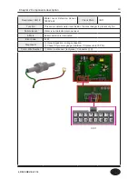
Page 27: ...ilure Event Water flow is not detected Effects Domestic hot water set point is not achieved Error Code N A Diagonostic Restart the appliance Visual inspection check flow sensor wiring for proper connection Color Wire Number Ground blue Connector Flow Signal white Connector DC 5V red Connector Chapter 2 Components description CN3 LP 528 REV 8 01 14 ...

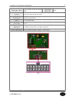
Page 28: ...ergy to ignite the fuel Failure Event sparks energy is not generated Effects The unit does not ignite Error Code Er11 Diagonostic Check wiring for proper connection Check range of voltage Color Wire Number Igniter red connector Igniter red connector Chapter 2 Components description CN9 LP 528 REV 8 01 14 ...

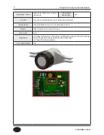
Page 29: ...ition fault Effects Abnormal product operation Error Code Er 11 Er 72 Diagonostic Check the discoloration of flame monitoring window Check the connection around the flame detection sensor Color Wire Number Flame detection sensor red connector Flame detection sensor black connector Chapter 2 Components description CN7 LP 528 REV 8 01 14 ...

Page 30: ...to open close Gas flow is not modulated Proportional gas valve Effects Spark is not generated Operation of product is stopped Carbon monoxide exceeding the reference is discharged Error Code Er 11 Diagonostic Check wiring for proper connection Check the connection and mounting location Check resistance using a multi meter Color Wire Number Gas valve purple connector ⓐ ⓑ ⓒ ⓓ ⓔ Chapter 2 Components ...

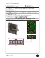
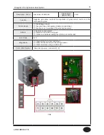
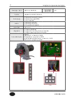
Page 31: ...mbustion Abnormal noise occurs The unit does not operate Error Code Er 41 Er 61 Diagonostic Check vent blockage Check BLDC fan wiring for proper connection Check voltage range using a multi meter Color Wire Number Blower GND blue ⓒ connector 30VDC Power white ⓔ connector 30VDC Speed feedback signal yellow ⓓ connector 14VDC VDD red ⓑ connector 30VDC ⓐ ⓑ ⓒ ⓓ ⓔ Chapter 2 Components description CN4 LP...

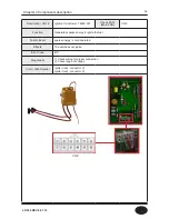
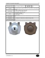
Page 32: ...s Failure Event Unable to initialize sustain combustion Soot occurs on the surface of burner Gas leakage occurs from burner Effects Abnormal combustion Unstable flame generation Ignition failure Error Code N A Diagonostic Visual inspection Unstable flame conditions during operation Color Wire Number N A Chapter 2 Components description LP 528 REV 8 01 14 ...

Page 33: ...ailure Event Water or exhaust gas leakage through the crack Abnormal heat exchange Effects Operation of product is stopped Exhaust gas leakage Abnormal noise occurs Error Code Er33 Er94 Diagonostic Check the crack on the surface of heat exchanger Check the boiling sounds inside the heat exchanger Color Wire Number N A Chapter 2 Components description LP 528 REV 8 01 14 ...

Page 34: ...e condensate generated by the combustion Failure Event Unneutralized condensate is discharged Effects Product corrosion and environmental degradation are caused by the condensate Error Code Er20 Diagonostic Check the hose for blockage or bending Color Wire Number N A Chapter 2 Components description LP 528 REV 8 01 14 ...

Page 35: ...s energy into DHW to provide stable temperature Failure Event Leakage occurs at DHW storage tank Effects Operation of product is stopped Domestic hot temperature fluctuation Error Code Er20 Diagonostic Replace DHW storage tank Color Wire Number N A Chapter 2 Components description LP 528 REV 8 01 14 ...

Page 36: ... Water flow is not detected Effects Unit does not opperate Internal CH DHW circulation pump is not operating Error Code N A Diagonostic Visual inspection check wiring for proper connection Check supply voltage Color Wire Number Internal DHW circulation pump yellow green Connector Internal CH primary circulation pump white Connector Chapter 2 Components description CN9 LP 528 REV 8 01 14 ...

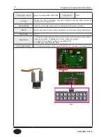
Page 37: ... not start Operation of product is stopped once water leakage is detected Error Code Er 66 Er 68 Diagonostic Restart the unit Check the connection around the mixing valve Color Wire Number IWM Inlet Water Modulation GND brown connector DHM Position Sensor orange connector DC 14V white connector DHM X phase black connector DHM Y phase red connector DC 14V blue connector DHM X phase green connector ...

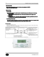
Page 38: ...rature is reached to 50 10 2 Stage2 After stage 1 operation if CH supply and DHW storage tank temperatures are below 41 5 second stage of this mode is operational and the burner is activated With the second stage both CH and DHW storage tank circu lation pumps are run until CH supply and or DHW storage tank temperature reaches 104 40 If the unit is powered off the internal circulation pumps operat...

Page 39: ...power off or breakout Safety function 1 Power supply After power is supplied for 5 sec boiler monitors in real time if power and Hz are safe range 1 1 Low power supply If power supply is below 93Vac 3V for 10 sec boiler stops combustion until power supply is 95Vac 3V 1 2 Frequency error With power supplied boiler chooses either 50Hz or 60Hz and if frequency reaches out of the range 5Hz for more th...

Page 40: ...38 Status display mode Control panel mode LCD Specification Chapter 3 How to use control panel LP 528 REV 8 01 14 ...

Page 41: ...39 Installer Setting Mode Control panel mode Chapter 3 How to use control panel LP 528 REV 8 01 14 ...

Page 42: ...40 Chapter 3 How to use control panel LP 528 REV 8 01 14 ...

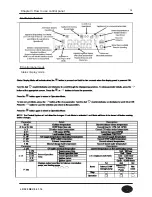
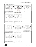
Page 43: ...120 Press hot water temperature control button to enter DHW temperature setting mode The default tempera ture is set 125 Domestic Hot Water high temperature control Range 121 140 Press hot water temperature button for 5 secs to set high temperature Turn the dial to set desired DHW temperature Press dial button to complete setting Press hot water temperature control button to enter DHW temperature ...

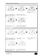
Page 44: ...gain to go back to the previous mode Press current status button with 0 ot mode to go back to initial status Press current status for 5 secs and 0 ot will show up Press dial button for 1 sec when 0 ot shows up Press dial button to complete setting Turn the dial to set desired heating water temperature Press Central heating temperature control button to enter temperature setting mode The default te...

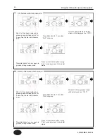
Page 45: ...b lt shows up Press dial button for 1 sec when A GA shows up Press dial button for a sec again to go back to the previous mode Press dial button for a sec again to go back to the previous mode Press current status button during b lt mode to go back to the initial status Press current status button during A GA mode to go back to the initial status Current return water temperature status will be dis...

Page 46: ...Check RPM by pressing dial button for 1 sec when c Fr shows up Press dial button for 1 sec when d Lc shows up Press dial button for a sec again to go back to c Fr mode Press dial button for a sec again after setting completion to go back to the previous mode Press current status button with c Fr mode to go back to the initial status Press current status button with d Lc mode to go back to the init...

Page 47: ...shows up Press dial button for 1 sec when F dH shows up Press dial button for a sec again to go back to the previous mode Press dial button for a sec again to go back to the previous mode Press current status button during E oP mode to go back to the initial status Press current status button during F dH mode to go back to the initial status Current supply water temperature status will be displaye...

Page 48: ...al button for a sec again to go back to the previous mode Press dial button for a sec again to go back to the previous mode Press current status button with H Eh mode to go back to the initial status Press current status button with I St mode to go back to the initial status Current exhaust gas temperature status will be displayed ex 130 Current hot water tank temperature status will be displayed ...

Page 49: ... back to the previous mode Press dial button for a sec again to go back to the previous mode Press current status button during J oH mode to go back to the initial status Current power input time will be shown ex 875 100hr Press current status button for a sec after confirmation to go back to the initial status Current hot overheating sensor tem perature status will be displayed ex 130 Turn the di...

Page 50: ...ows up Press dial button for a sec when 3 rh shows up Current power input time will be shown ex 375hr Press current status button for 1 sec after confirmation to go back to the initial status Press current status button for 1 sec after confirmation to go back to the initial status Current power input time will be shown ex 75 1000hr 75 000hr Turn the dial until 2 rh shows up Turn the dial until 3 r...

Page 51: ...for a sec when 5 IH shows up Press current status button for 1 sec after confirmation to go back to the initial status Press current status button for 1 sec after confirmation to go back to the initial status Current ignition attempts number will be shown ex 175 10times 1750times Current ignition attempts number will be shown ex 95 10000 times 950 000times Turn the dial until 4 lt shows up Turn th...

Page 52: ...status button for 5 secs turn the dial until it shows P ou Check RPM by pressing volume button for 1 sec when P ou shows up Press current status button with P ou mode to go back to the initial status Pump condition current status will be displayed Pump Condition Display LP 528 REV 8 01 14 ...

Page 53: ...o set on status when initial of shows up Default off mode Press current status button after confirmation to go back to the initial status Press dial button during on status to save the setting Press dial button for a sec to access the codes Press dial button for a sec when 2 cE is displayed Press current status button for a sec to go back to initial status after confirmation Fault Code history Cha...

Page 54: ...l to set Li when initial GA shows Convert Liter to Gallon Press dial button during on status to save the setting Press dial button to save the setting during Li status Press dial button for a sec when 3 In is displayed Press current status button for a sec to go back to initial status after confirmation Press dial button for a sec when 4 Fu is displayed Press current status button for a sec to go ...

Page 55: ...ck to initial status after confirmation Internal Storage Tank Pre heating Mode on or off Chapter 3 How to use control panel Press current status button for 5 secs while display is powered off to enter into installer setting mode Turn the dial until 6 oH shows up Turn the dial to the desired setting when initial 68 setting is displayed Press dial button to save the setting Press dial button for a s...

Page 56: ...Press dial button for a sec when 8 FH is displayed Fan Max RPM Adjustment Chapter 3 How to use control panel Press current status button for 5 secs while display is powered off to enter into installer setting mode Turn the dial until 7 oL shows up Turn the dial to the desired setting when initial 5 setting is displayed Press dial button to save the setting Press dial button for a sec when 7 oL is ...

Page 57: ...layed 30 30 Default 0 Turn the dial to on status when initial off shows up Default off Press dial button to save the setting Press dial button to save the setting Press dial button for a sec when 9 FL is displayed Press dial button for a sec when 10 dr is displayed Fan Min RPM Adjustment Reset burner operation time Press current status button for a sec to go back to initial status after confirmati...

Page 58: ...t off Turn the dial to the desired setting when initial 0 is displayed Range 0 120 min Default 0 min Press dial button to save the setting Press dial button to save the setting Press dial button for a sec when 11 dl is displayed Press dial button for a sec when 12 bt is displayed Reset igniting cycles Boost Function Press current status button for a sec to go back to initial status after confirmat...

Page 59: ... Default 1 min Turn the dial to the desired setting when initial setting is displayed Range 9 27 Default 27 Press dial button to save the setting Press dial button to save the setting Press dial button for a sec when 13 Ft is displayed Press current status button for a sec to go back to initial status after confirmation Press current status button for a sec to go back to initial status after confi...

Page 60: ...rn the dial to the desired setting when initial setting is displayed Range miniimum supply tempera ture 9 180 Default 180 Press dial button to save the setting Press dial button to save the setting Press dial button for a sec when 15 OF is displayed Press current status button for a sec to go back to initial status after confirmation Press current status button for a sec to go back to initial stat...

Page 61: ...temperature 9 Default 86 Turn the dial to the desired setting when initial setting is displayed Range 120 140 Default 140 Press dial button to save the setting Press dial button to save the setting Press dial button for a sec when 17 cL is displayed Press dial button for a sec when 18 dH is displayed Minimun CH Supply tempature Maximum DHW set temperature Press current status button for a sec to g...

Page 62: ...nge 50 100 Default 100 Turn the dial to the desired setting when initial setting is displayed Range 50 100 Default 100 Press dial button to save the setting Press dial button to save the setting Press dial button for a sec when 19 cb is displayed Press dial button for a sec when 20 db is displayed CH capacity DHW heating capacity Press current status button for a sec to go back to initial status a...

Page 63: ...e dial to the desired setting when initial setting is displayed Range 1min 60min Default 5min Press dial button to save the setting Press dial button to save the setting Press dial button for a sec when 21 PP is displayed Press dial button for a sec when 22 Po is displayed Internal CH primary pump post run timer T T calling for heat Internal CH pump overrun timer On Press current status button for...

Page 64: ... 10min Turn the dial to the desired setting when initial setting is displayed Range 140 167 Default 158 Press dial button to save the setting Press dial button to save the setting Press dial button for a sec when 23 PF is displayed Press dial button for a sec when 24 SF is displayed Internal CH pump overrun timer Off Internal DHW storage tank set point Press current status button for a sec to go b...

Page 65: ...ayed Range 9 36 Default 27 Turn the dial to the desired setting when initial setting is displayed Press dial button to save the setting Press current status button for a sec to go back to initial status after confirmation Press dial button for a sec when 25 So is displayed Press dial button for a sec when 26 dt is displayed Internal DHW storage tank differential Delay time when switching from DHW ...

Page 66: ...is displayed Range 1min 60min Default 10min Turn the dial to the desired setting when initial setting is displayed Press dial button to save the setting Press dial button to save the setting Press dial button for a sec when 27 PE is displayed Press dial button for a sec when 29 AP is displayed Internal CH primary pump post purge timer T T satisfied Internal CH and DHW pumps test mode Press current...

Page 67: ...65 Chapter 4 Troubleshooting 1 Flame Detection LP 528 REV 8 01 14 ...

Page 68: ...66 2 Gas Detection 3 APS Burner overheat limit Condensate Block switch APS Burner overheat limit Condensate Block IT OFF GV OFF ERROR E29 Chapter 4 Troubleshooting LP 528 REV 8 01 14 ...

Page 69: ...67 4 Storage DHW OP CH Overheat Exhaust Overheat Sensor Chapter 4 Troubleshooting LP 528 REV 8 01 14 ...

Page 70: ...68 Error code Chapter 4 Troubleshooting LP 528 REV 8 01 14 ...

Page 71: ...69 Chapter 4 Troubleshooting LP 528 REV 8 01 14 ...

Page 72: ...70 Chapter 4 Troubleshooting LP 528 REV 8 01 14 ...

Page 73: ...eset Check point If the flame sensing viewing port is exces sively discolored loss of fame will occur Ensure gas valve wiring is properly connected Please check flame detector sensor s connecting line and ensure correct position as shown Check Gas Inlet Pressure Range NG 3 5 WC 14 WC LP 3 5 WC 14 WC Please check the blockage of flue intake and exhaust pipes If all things are normal please replace ...

Page 74: ...ure Range NG 3 5 WC 14 WC LP 3 5 WC 14 WC If the flame sensing viewing port is excessively discolored loss of fame will occur To correct this problem replace the flame viewing glass From more than DC 2 5V after ignition safety cut off will appear When setting before ignition is less than DC 2 5V Re place flame sensor When setting after ignition is more than DC 2 5V Replace flame sensor If all thin...

Page 75: ...he factory settings assure that default settings are set to correct overheating condition Check internal CH pump is operational Use a flat head screw driver to rotate a screw on the back side of the pump to ensure the pump internal shaft is not stuck Check pump wiring to ensure proper connection Please check CH supply temperature sensor wires are tagged OP When the value measured with a multi mete...

Page 76: ... reset When condensate outlet blockages occurs error code Er 20 will appear Failure event If the condensate drain line is blocked Er 20 will occur Check point Check Condensate discharging line Check APS line for proper connection Chapter 4 Troubleshooting LP 528 REV 8 01 14 ...

Page 77: ...supply over heating sensor connected to heat exchanger is shorted or disconnected Er 28 is displayed Check point Check whether over heating switch is shorted or disconnected Check CH supply over heating sensor condition Connect multi meter with over heating switch s sock et and measure the value If value shows 0Ω it s a sensor s malfunction so replace it Chapter 4 Troubleshooting LP 528 REV 8 01 1...

Page 78: ... Er 29 is displayed Check point Check APS wiring to assure proper connection Check APS hose check hose damages Please check the blockage of flue exhaust pipe If the above conditions are normal please replace APS If all things are normal please replace main controller Chapter 4 Troubleshooting WARNING Failure to turn the power off to the appliance before repair could result in serious injury or dea...

Page 79: ...ion Check point If all things are normal please replace main controller Ensure the storage tank temperature sensor is properly connected Check storage tank temperature sensor condition When the resistance value measured with a multimeter is 0Ω replace storage tank temperature sensor Chapter 4 Troubleshooting WARNING Failure to turn the power off to the appliance before repair could result in serio...

Page 80: ...ion Check point Ensure the DHW outlet temperature sensor is properly connected If all things are normal please replace main controller Chapter 4 Troubleshooting Check DHW outlet temperature sensor condition When the resistance value meas ured with a multimeter is 0Ω replace DHW outlet temperature sensor WARNING Failure to turn the power off to the appliance before repair could result in serious in...

Page 81: ...e disconnected or faulty Check point Ensure the CH supply temperature sensor is properly connected Check CH supply temperature sensor condition When the resistance value measured with a multimeter is 0Ω replace CH supply If all things are normal please replace main controller Chapter 4 Troubleshooting WARNING Failure to turn the power off to the appliance before repair could result in serious inju...

Page 82: ...ion Check point If all things are normal please replace main controller Check exhaust temperature sensor condition When the resistance value measured with a multimeter is 0Ω replace exhaust temperature sensor Ensure the exhaust temperature sensor is properly connected Chapter 4 Troubleshooting WARNING Failure to turn the power off to the appliance before repair could result in serious injury or de...

Page 83: ...omatically reset Failure event Incoming voltage issue Check point Ensure manual power switch is properly connected Check the supply voltage at the manual power switch is within 102V 132 Vac if so then it s main controller s malfunction and replace it Check whether power voltage is within the safety scope 5 seconds after power is supplied Chapter 4 Troubleshooting LP 528 REV 8 01 14 ...

Page 84: ...y is not in the range of 50 60 Hz 5Hz all the outputs will malfunction except for the fan post purge Failure event Incoming frequency issue Check point When operating power frequency is within 50 60 HZ 5Hz error will automatically reset Chapter 4 Troubleshooting LP 528 REV 8 01 14 ...

Page 85: ...top except fan post purge Failure event When EEPROM malfunctions error occurs and all of the outputs will stop except fan post purge Check point Replace the main controller Chapter 4 Troubleshooting WARNING Failure to turn the power off to the appliance before repair could result in serious injury or death LP 528 REV 8 01 14 ...

Page 86: ... on all related gas pipe connection and gas valve to determine source of leak Once determined repair leak and reassemble Check condition of O rings and gaskets and replace them if damaged If leaks are not present on the gas piping or valve Start unit and monitor for leaks around blower assembly and connection to determine source of leaks If all things are normal please replace main controller Chap...

Page 87: ... fan speed Check point Check whether error code disappears after turning OFF and ON the power Check vent blockage Check whether BLDC fan is operating normally If all things are normal please replace main controller Chapter 4 Troubleshooting WARNING Failure to turn the power off to the appliance before repair could result in serious injury or death LP 528 REV 8 01 14 ...

Page 88: ...ture sensor 3 Overheating sensor and water temperature sensor are inspected but same problem occurs Replace main controller If above issues operates normally replace main controller Chapter 4 Troubleshooting Check whether error code disappears after turning OFF and ON the power Check whether error code disappears after turning OFF and ON the power Check whether error code disappears after turning ...

Page 89: ...tortion or burn marks If plate shows signs of overheating replace entire burner plate assembly Check burner overheat switch connections Ensure all wire leads are secure After removing the burner overheat switch from the burner plate measured resistance using multi meter If the resistance value is 0Ω replace the switch If all things are normal please replace main controller Chapter 4 Troubleshootin...

Page 90: ...t blockage If all things are normal please replace main controller Check whether BLDC fan is operating normally Although fan operation is normal replace the fan in case the speed is higher than the reference value Chapter 4 Troubleshooting WARNING Failure to turn the power off to the appliance before repair could result in serious injury or death LP 528 REV 8 01 14 ...

Page 91: ...xing Valve recognizes zero point after turning off and on the power Check indication of error after basically turning off and on the power If mixing valve doesn t operate normally replace the part If all things are normal please replace main controller Chapter 4 Troubleshooting WARNING Failure to turn the power off to the appliance before repair could result in serious injury or death LP 528 REV 8...

Page 92: ... Check point Mixing Valve recognizes zero point after turning off and on the power Check indication of error after basically turning off and on the power If mixing valve doesn t operate normally replace the part If all things are normal please replace main controller Chapter 4 Troubleshooting WARNING Failure to turn the power off to the appliance before repair could result in serious injury or dea...

Page 93: ...ecting line and ensure correct position as shown From more than DC 2 5V after ignition safety cut off will appear When setting before ignition is less than DC 2 5V Replace flame sensor When setting after ignition is more than DC 2 5V Replace flame sensor Flame detector sensor setting Please check after closing front cover If all things are normal please replace main controller Chapter 4 Troublesho...

Page 94: ... 76 is displayed Failure event Connection error between LCD display panel and main controller Check point Ensure proper connection between display panel and main controller If all things are normal please replace main controller Chapter 4 Troubleshooting WARNING Failure to turn the power off to the appliance before repair could result in serious injury or death LP 528 REV 8 01 14 ...

Page 95: ...per connection If CH pressure is lower than 15 PSI check automatic Water feed valves to as sure they are operating properly Check to ensure automatic air vent operates properly Either there is no sufficient wa ter or there is air trapped in the system Check freezing condition of the water replenishment line Visually check leakage around the internal CH piping then check boiler near piping for leak...

Page 96: ...81 appears Failure event Low water level circuit error Check point Ensure the low water level sensor is properly connected If all things are normal please replace main controller Chapter 4 Troubleshooting WARNING Failure to turn the power off to the appliance before repair could result in serious injury or death LP 528 REV 8 01 14 ...

Page 97: ...pears Check point Check whether operation of boiler is normal after turning display panel off on Check internal CH and DHW pumps are operational Use a flat head screw driver to rotate a screw on the back side of the pump to ensure the pump internal shaft is not stuck Check pumps wiring to ensure proper connection Ensure storage tank and CH supply temperature sensor are properly connected OP sensor...

Page 98: ...t when exhaust temperature is below 180 F Failure event Exhaust temperature overheating issue Check point Ensure exhaust temperature sensor is properly connected Check main controller connection Check Exhaust Temperature sensor condition when the resistance value meas ured with a multimeter is 0Ω replace exhaust temperature sensor Chapter 4 Troubleshooting LP 528 REV 8 01 14 ...

Page 99: ...ing gas mixer and fan 10 Attach Fan and gas mixer and tighten with three screws 11 Attach fan on the burner and put gas mixer into exhaust pipe 12 Fix fan by tightening the four screws in the condition placed FAN on the burner upper case 13 Connect venturi and gas pipe and assemble a nut 14 Connect wire connector on the fan 15 Switch water valve to open 16 Switch manual power switch to open 17 Swi...

Page 100: ...ected to gas valve bottom 9 Replace gas valve with new component after separating a adapter 10 Tighten each four screws to assemble adapter on the gas valve upper bottom 11 Tighten two screws after fixing adapter on right side of boiler 12 Connect gas valve and gas pipe and assemble a nut 13 Connect wire connector on the gas valve 14 Switch water valve to open 15 Switch manual power switch to open...

Page 101: ...e s 2 Switch manual power switch to 120V OFF 3 Switch water valve to close 4 Separate wire connector connected to mixing valve 5 Separate two clips fixing the mixing valve 6 Replace mixing valve with new component 7 Assemble flow sensor and pipe and fix mixing valve with two clips 8 Connect wire connector on the mixing valve 9 Switch water valve to open 10 Switch manual power switch to open 11 Swi...

Page 102: ... operate normally 1 Switch main gas valve to close s 2 Switch manual power switch to 120V OFF 3 Switch water valve to close 4 Open water drain valve to drain water in boiler 5 Separate wire connector connected to circulation pump for heating 6 Loosen two screws for separating pipe connected with circulation pump for heating 7 Replace circulation pump for heating with new component after separating...

Page 103: ... drain valve 11 Switch water valve to open 12 Switch manual power switch to open 13 Switch main gas valve to open 14 Test whether it operate normally 1 Switch main gas valve to close s 2 Switch manual power switch to 120V OFF 3 Switch water valve to close 4 Separate wire connector connected to flame detection sensor 5 Flame detection sensor is rotated 45 degrees clockwise 6 Pull forward the flame ...

Page 104: ...w component 8 After fixing the new main controller to bracket tighten two screws both side of main controller 9 Assemble wire connectors on main controller 10 Switch water valve to open 11 Switch manual power switch to open 12 Switch main gas valve to open 13 Test operation NOTE When assemble connector check wiring color and spot to avoid mistake Chapter 5 Replacement Instructions LP 528 REV 8 01 ...

Page 105: ...r from the bracket 8 Assemble ignition transformer on the bracket after replacing with new component 9 Assemble ignition transformer at the original position 10 Assemble ports 11 Switch water valve to open 12 Switch manual power switch to open 13 Switch main gas valve to open 14 Test whether it operate normally NOTE 1 Check part is properly secured 2 Check normal operation Chapter 5 Replacement In...

Page 106: ...104 1 Cabinet Replacement Parts Chapter 7 Repair Part Diagram LP 528 REV 8 01 14 ...

Page 107: ...105 Chapter 7 Repair Part Diagram LP 528 REV 8 01 14 ...

Page 108: ...106 2 Combustion System Replacement Parts Chapter 6 Repair Parts Diagram LP 528 REV 8 01 14 ...

Page 109: ...107 Chapter 7 Repair Part Diagram LP 528 REV 8 01 14 ...

Page 110: ...108 Memo LP 528 REV 8 01 14 ...

Page 111: ...109 Memo LP 528 REV 8 01 14 ...

Page 112: ...110 Memo LP 528 REV 8 01 14 ...

Reviews: